HOME
TitleShort-Hidden -42
©
National Instruments Corporation
Configure and Install Your GPIB-PCII/IIA
Next
Step
Previous
Step
42
6 7
Interrupt
Disabled
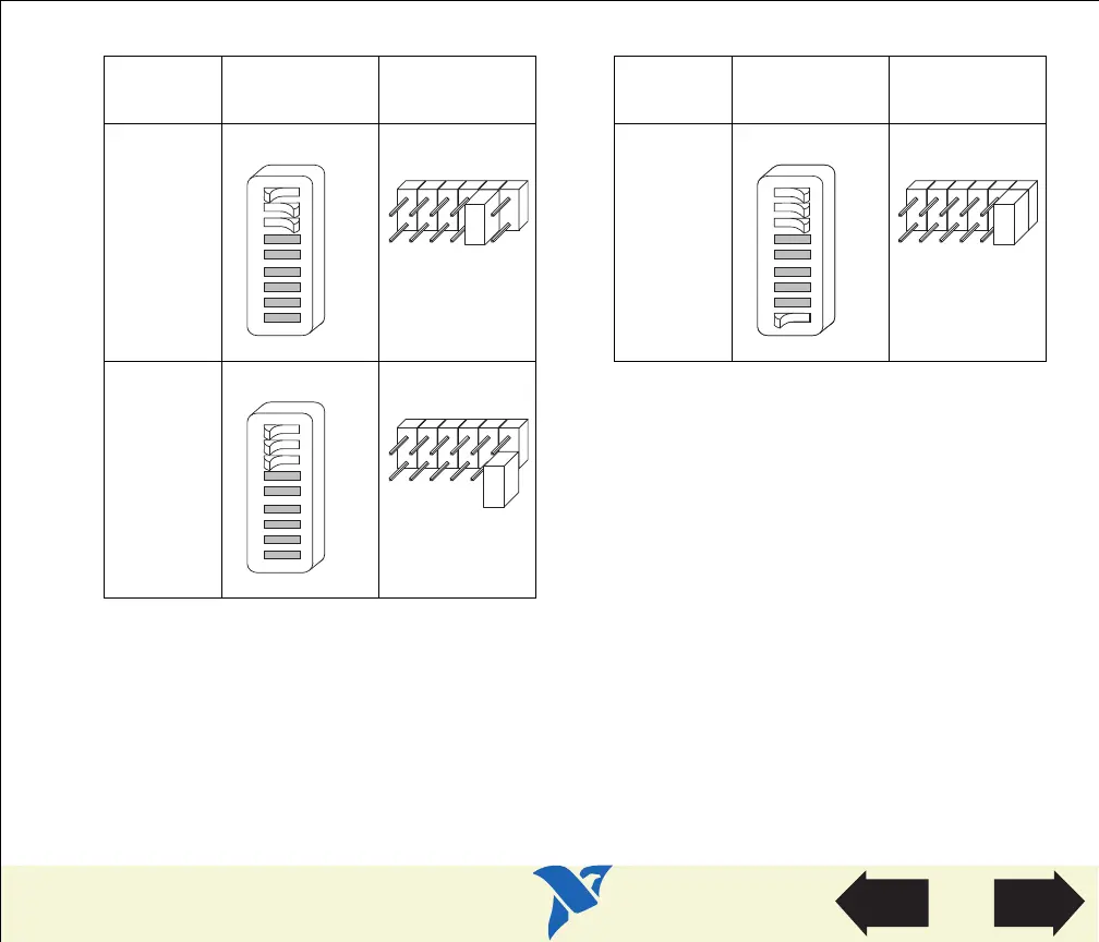
Table 8. Interrupt Request Settings for GPIB-PCII/IIA in PCIIA Mode (Continued)
Interrupt
Line
Switch Jumper
Interrupt
Line
Switch Jumper
I2
I1
I0
U210
1 26897345
OFF
IRQ2
IRQ3
IRQ4
IRQ5
IRQ6
IRQ7
I2
I1
I0
U210
1 26897345
OFF
I2
I1
I0
U210
1 26897345
OFF
IRQ2
IRQ3
IRQ4
IRQ5
IRQ6
IRQ7
I2
I1
I0
U210
1 26897345
OFF
IRQ2
IRQ3
IRQ4
IRQ5
IRQ6
IRQ7
The remaining steps in the installation and configuration process are the same for GPIB-PCII mode
and GPIB-PCIIA mode. Click here to go to the section Configure the GPIB-PCII/IIA DMA Channel,
and continue configuring and installing your GPIB-PCII/IIA.
View Parts
Locator
Diagram
 Loading...