Control System 41Service Manual – SC2000
Function Electronic Board (EB1) Connectors (Continues)
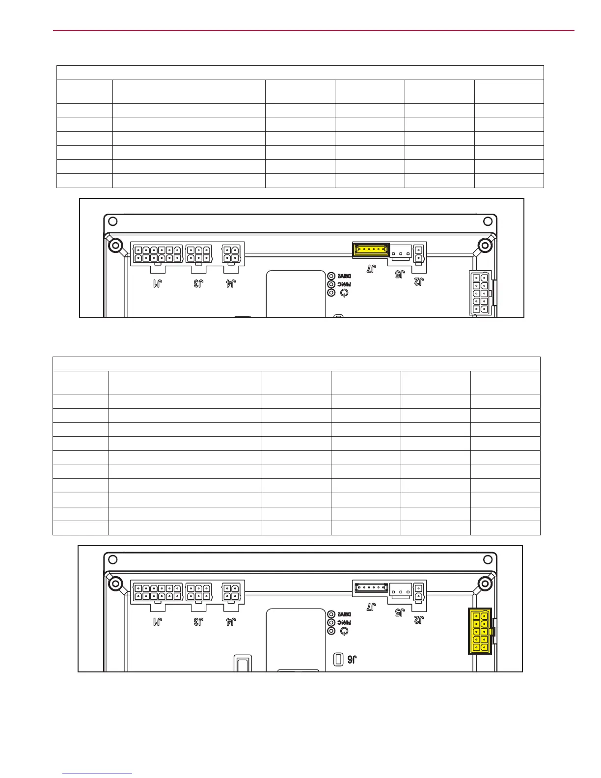
(Figure 27) J7: TYCO MODU II type, 6-ways vertical
PIN Description Electronic board
in/out
V ref. I max. Connected to
1
+24V power supply out 24V <1A TRK.RD
2
+5V power supply out 5V <1A -
3
iButton input in (out) 0V (0-5V) <1A TRK.YE
4
External time counter enabled (in) out 0V (0-24V) <1A TRK.WH
5
Power supply - out 0V <1A TRK.BU
6
Machine on signal out 24V <1A TRK.BN
Figure 27
(Figure 28) J8: TYMOLEX MINIFIT type, 10-ways vertical
PIN Description Electronic board
in/out
V ref. I max. Connected to
1
Solenoid valve power supply - out 0V 1A EV1
2
Detergent pump power supply - out 0V <1A M4
3
Electromagnetic brake output out 0V 1A BRK
4
Opt power supply - out 0V 1A USB -
5
DECK congurator return in 0V <1A J4.10
6
Solenoid valve power supply + out 24V 1A EV1
7
Detergent pump power supply + out 24V <1A M4
8
Electromagnetic brake output + out 24V 1A BRK
9
Opt power supply + out 24V 1A USB +
10
Power supply for DECK congurator out 0V <1A J4.4
Figure 28

 Loading...


