Control System 42Service Manual – SC2000
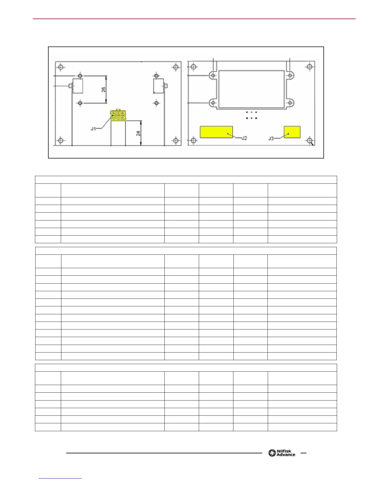
Display Electronic Board (EB2) Connectors
Figure 29
(Figure 29) J1: MOLEX MINIFIT type, 6-ways vertical
Ref. Description
Electronic
board in/out
V ref. I max. Connected to
1 Power supply + in 24V 3A CFG2.J1.6
2 Machine startup enabling out 24V 3A CFG2.J1.7
3 Display electronic board serial + in/out 5V <1A CFG2.J1.8
4 Display electronic board serial - in/out 0V <1A CFG2.J1.9
5 Power supply - in 0V <1A CFG2.J1.5
6 Power supply repetition - out 0V <1A -
(Figure 29) J2: FCI DUFLEX (2.54 pitch) 9-way, male pins
Ref. Description
Electronic
board in/out
V ref. I max.
1 Power supply - common out 0V <1A
2 HORN button (P3) in 0V <1A
3 EDS button (P2) in 0V <1A
4 DETERGENT MIX button (P1) in 0V <1A
5 BRUSH / EXTRAPR. button (P4) in 0V <1A
6 VACUUM button (P5) in 0V <1A
7 BRUSH RELEASE button (P6) in 0V <1A
8 ON/OFF button (P0) in 0V <1A
9 REVERSE GEAR button (P7) in 0V <1A
10 INCREASE SPEED button (P8) in 0V <1A
11 DECREASE SPEED button (P9) in 0V <1A
12 Dashboard congurator in 0V <1A
(Figure 29) J3: FCI DUFLEX (2.54 pitch) 6-way, male pins
Ref. Description
Electronic
board in/out
V ref. I max.
1 Power supply – common out 0V <1A
2 BRUSH RELEASE function LED (LD3) out 5V <1A
3 VACUUM function LED (LD2) out 5V <1A
4 BRUSH / EXTRAPR funct. LED (red) (LD1R) out 5V <1A
5 BRUSH / EXTRAPR funct. LED (green) (LD1V) out 5V <1A
6 SPOT function LED (LD4) out 5V <1A

 Loading...


