Solution System 74Service Manual – SC2000
Solution System
Functional Description
The solution system supplies water and detergent to
the brush when cleaning the oor. The solution tank is
also the main machine body. There is a manual valve
on the left side of the tank, just under the rear wheel,
to close the water supply whenever maintenance must
be performed on the machine. The solution ows from
the tank to the valve, through the lter and solenoid
valve (EV1) and then to the brush deck.
The detergent pump (M4), present only on EcoFlex™
systems, controls the ow of detergent from the Eco-
Flex™ tank which is then transported to the ow
in the main tube just before the solution enters the
brush deck.
The EcoFlex™ system can be selected with the spe-
cic lever under the steering wheel.
The quantity of detergent is dened by the operator
via the buttons on the dashboard instrument elec-
tronic board (EB4).
Solution ow levels 1, 2 and 3 regulate the ow of so-
lution on the basis of the machine speed so as to keep
the quantity of solution dispensed per square metre of
oor treated constant (for further details and modi-
cations, see the corresponding paragraph in the chap-
ter Control System).
Located centrally, below the solution tank, there is
also a hole for draining any liquid in the battery com-
partment.
The solution ow is regulated by various timed ON /
OFF cycles, according to:
• Water ow rate adjustment (0 - 4)
• Solution tank level
Both the solenoid valve and detergent pump (when
the EcoFlex™ system is enabled) follow the same tim-
ings.
The solenoid valve and detergent pump operate only
with the following inputs/conditions:
• Driver’s seat microswitch closed
• Brush function on
• Forward pedal pressed
• Battery level not critical, display icon without
segments and ashing outline.
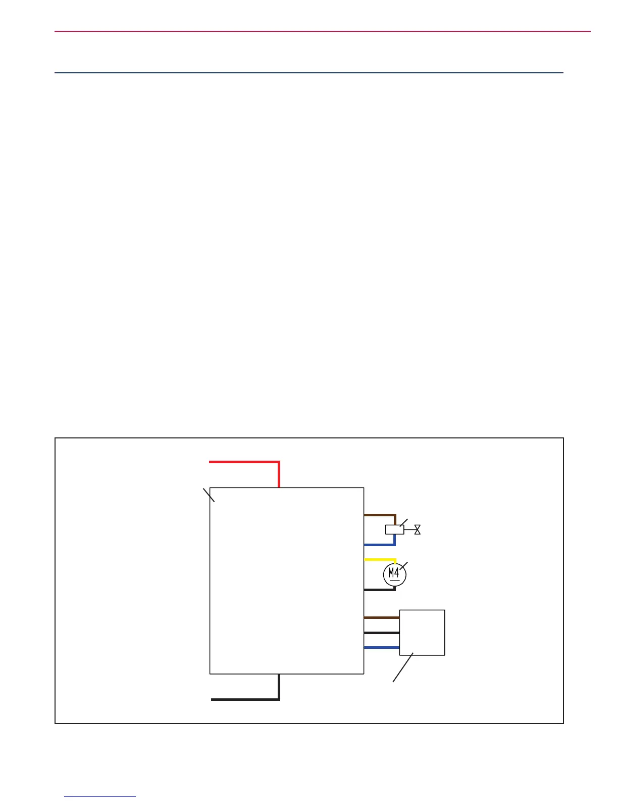
Wiring Diagram
OUT
-
+
J8.2
J8.1
J8.7
B+
B -
Electronic board power supply +
Electronic board power supply -
J5.1
J5.2
J5.3
Power supply for water level sensor +
Water level sensor return
Power supply for water level sensor -
Detergent pump power supply -
Solenoid valve power supply -
Detergent pump power supply +
FUNCTION
ELECTRONIC
BOARD (EB1)
SOLENOID VALVE
(EV1)
ECOFLEX™ PUMP
(M4)
SOLUTION LEVEL
SENSOR (SW1)
J8.6Solenoid valve power supply +
Figure 1

 Loading...


