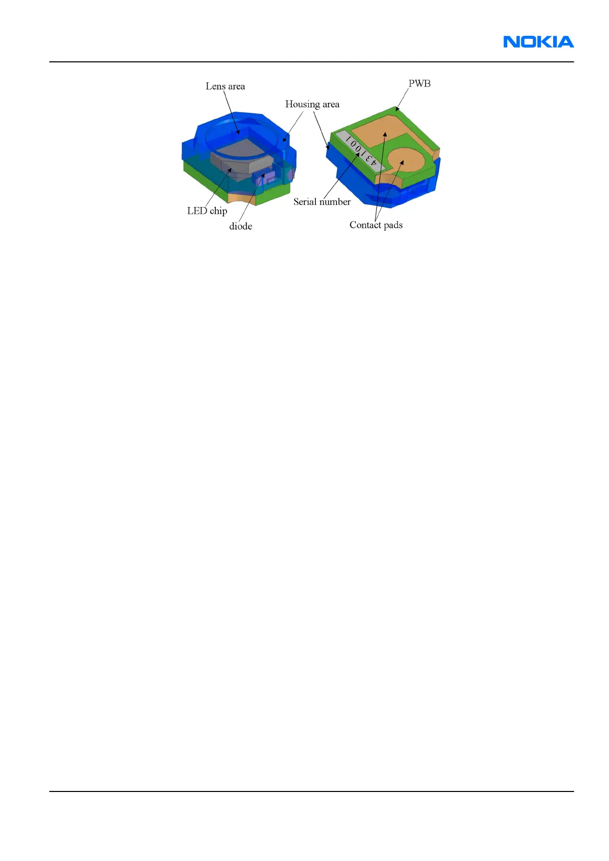
Figure 85 Mechanical construction of the flash LED module
The flash LED module as a component is not a repairable part, meaning that. components or parts in the
module cannot be changed. Only cleaning dust from the lens is allowed using clean compressed air.
The main parts of the module are:
• Housing, which is glued to the PWB
• Lens area (round area on top of the housing with circle patterns)
• LED chip (yellow chip inside the housing), which is soldered to the PWB
• ESD protection diode (black passive component inside the housing), which is soldered to the PWB
• PWB
• Contact pads
• Laser marked serial number
The flash LED is fixed to the phone mechanics with special clips. The contacts to the main PWB are formed
by using spring connectors.
Analysing image quality
Possible faults in image quality
When checking for possible errors in the flash functionality, knowing what error is suspected, significantly
helps the testing by narrowing down the number of possible test cases. The following types of image quality
problems may be expected to appear:
• LED module is not flashing at all
• Image colours are not good
• Flash power is weak
Testing flash module functionality
Context
With the help of this test you can check the flash module's overall functionality.
Always set the flash to FORCED FLASH mode when performing the test. The FORCED FLASH mode enforces the
LED module to flash, even if there is some ambient light present.
Steps
1. Take an image with the flash and monitor at same time whether the LED module flashes.
RM-180
Camera Module Troubleshooting Nokia Customer Care
Issue 1 COMPANY CONFIDENTIAL Page 8 –23
Copyright © 2006 Nokia. All rights reserved.
 Loading...