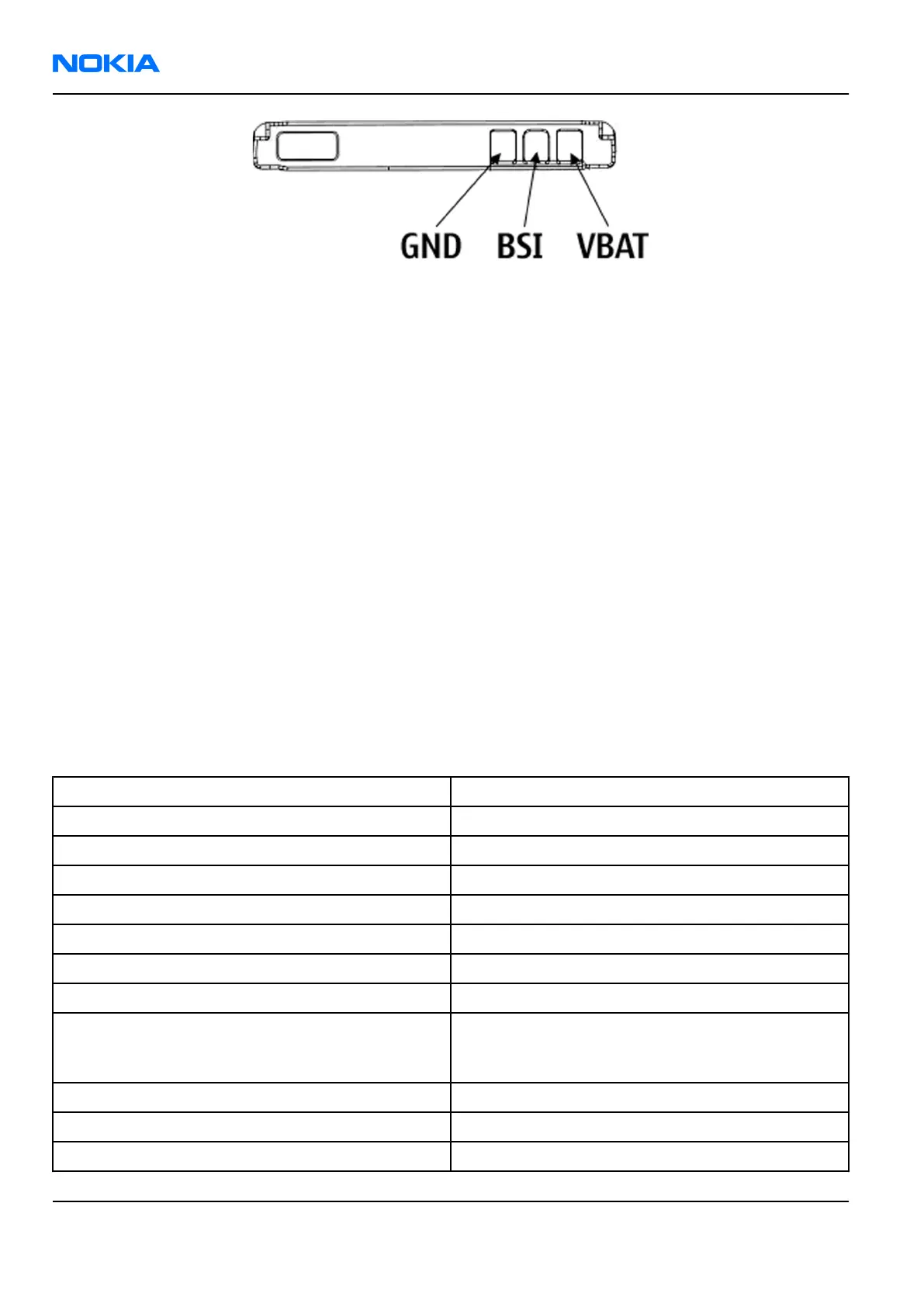
Figure 93 Battery pin order
Battery temperature is estimated by measuring separate battery temperature NTC via the BTEMP line, which
is located on the transceiver PWB, at a place where the phone temperature is most stable.
For service purposes, the device SW can be forced into local mode by using pull down resistors connected to
the BSI line.
Camera interface
Camera interface
The device uses a 2.0 megapixel camera module with a sensor resolution of 1600 x 1200. The following block
diagram shows how a CCP bus is used to transfer image data from the camera module to the phone engine.
This bi-directional control bus is a software-implemented I2C interface.
The camera regulator N1470 powers the digital parts of the camera, and a camera regulator N1471 is used
for powering the analogue parts.
A CAMVCTRL signal (Vctrl) is used for activating the camera module. When the Vctrl signal is Low, the module
enters the power on mode. When the signal is High, the module enters the power off mode.
A CAMCLK signal feeds the system clock for the camera module.
Camera construction
This section describes the mechanical construction of the camera module for getting a better understanding
of the actual mechanical structure of the module.
Table 16 Camera specifications
Sensor type CMOS Sensor
Photo detectors 1.9 million
F number/Aperture f/3.2
Focal length 4.8 mm (35 mm equivalent 37 mm)
Focus range 64 cm to infinity
Still Image resolutions 1600x1200, 640x480
Still images file format EXIF (JPEG), *.jpg
Video resolutions 352x288, 176x144. Both at 30 frames per second
Video clip length 10 seconds or free, maximal clip length in free mode
is 1 hour (limited by the data storing capabilities of
the device)
Video file format 3GPP, *.3gp
Exposure Automatic
White Balance Automatic
RM-180
Nokia Customer Care System Module
Page 9 –18 COMPANY CONFIDENTIAL Issue 1
Copyright © 2006 Nokia. All rights reserved.
 Loading...