Name of Connection Connector reference
Earpiece B2101
IHF speaker B2102
UI connections
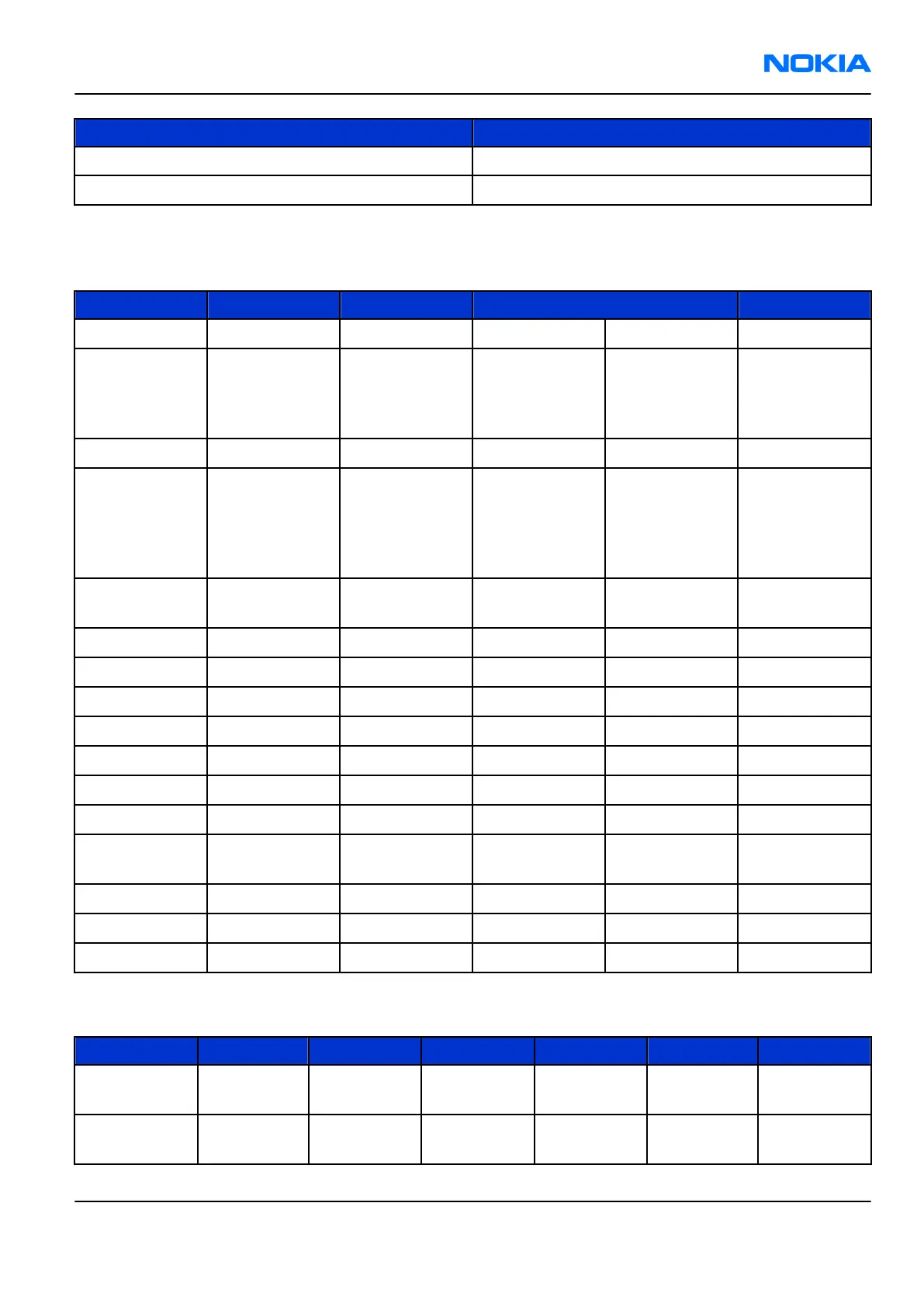
Table 26 User interface connections
Pin Signal I/O Engine connection Notes
1 GND GND
2 LED+ <- N2301 VLEDOUT2
Discrete
Backlight SMPS
(controlled by
EM ASIC N2300)
3 Col2 -> D4800 Kbc_2
4 LED-
->
R2305 + V2300 SETCURR2
Serial resistor +
Transistor
switch
(controlled by
EM ASIC N2300)
5 Col1
->
D4800 Kbc_1
Voice switch
connection
6 GND GND
7 Row3 -> D4800 Kbr_3
8 Row2 -> D4800 Kbr_2
9 Row1 -> D4800 Kbr_1
10 Row6 -> D4800 Kbr_6
11 Row0 -> D4800 Kbr_0
12 Col0 -> D4800 Kbc_0
13 Row5 -> D4800 Kbr_5
Voice switch
connection
14 Row4 -> D4800 Kbr_4
15 GND GND
16 Col3 -> D4800 Kbc_3
Keyboard interface electrical characteristics
Description Parameter Min Typ Max Unit Notes
High-level
input voltage
V
IH
0.65* V
DDS
V
DDS
0.3+ V
DDS
V Row
Low-level
input voltage
V
IL
-0.3 0 0.35* V
DDS
V Row
RM-180
System Module Nokia Customer Care
Issue 1 COMPANY CONFIDENTIAL Page 9 –39
Copyright © 2006 Nokia. All rights reserved.
 Loading...