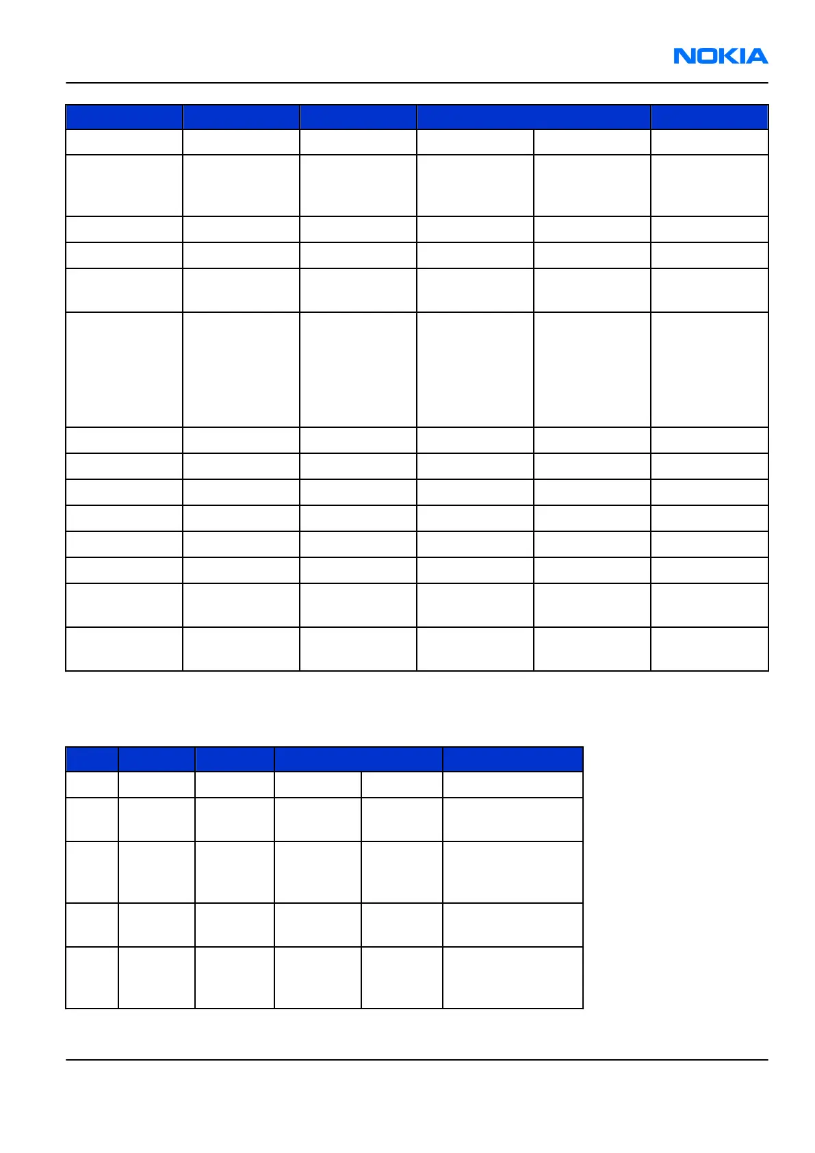
Pin Signal I/O Engine connection Notes
11 GND
12
LEDin
<- N2301 VLEDOUT1
N2301 is
controlled by
N2300
13 LEDout -> R2304 SETCURR1 Sink resistor
14 GND
15
CSX
<- D4800 Lcdcsx
Chip Select
(active low)
16
D/CX
<- D4800 Lcdcmd
Data/
Command
select
(high=data,
low
=command)
17 GND
18 D7 <-> D4800 Lcdda7 Data
19 D6 <-> D4800 Lcdda6 Data
20 D5 <-> D4800 Lcdda5 Data
21 D4 <-> D4800 Lcdda4 Data
22 TE -> D4800 Te Tearing Effect
23
RDX
<- D4800 Lcdrdx
Read Enable
(active low)
24
RESX
<- D4800 Gpio_60
Reset (active
low)
Camera interface connections and electrical characteristics
Table 28 Camera interface connections
Pin Signal I/O Engine connection Notes
1 GND
2 SDA <-> D4800 sda
I2C serial control
bus data
3 D+ -> D4800 Ccpdap
Differential serial
data, positive
node
4 SCL <- D4800 scl
I2C serial control
bus clock
5 D- -> D4800 Ccpdan
Differential serial
data, negative
node
RM-180
System Module Nokia Customer Care
Issue 1 COMPANY CONFIDENTIAL Page 9 –41
Copyright © 2006 Nokia. All rights reserved.
 Loading...