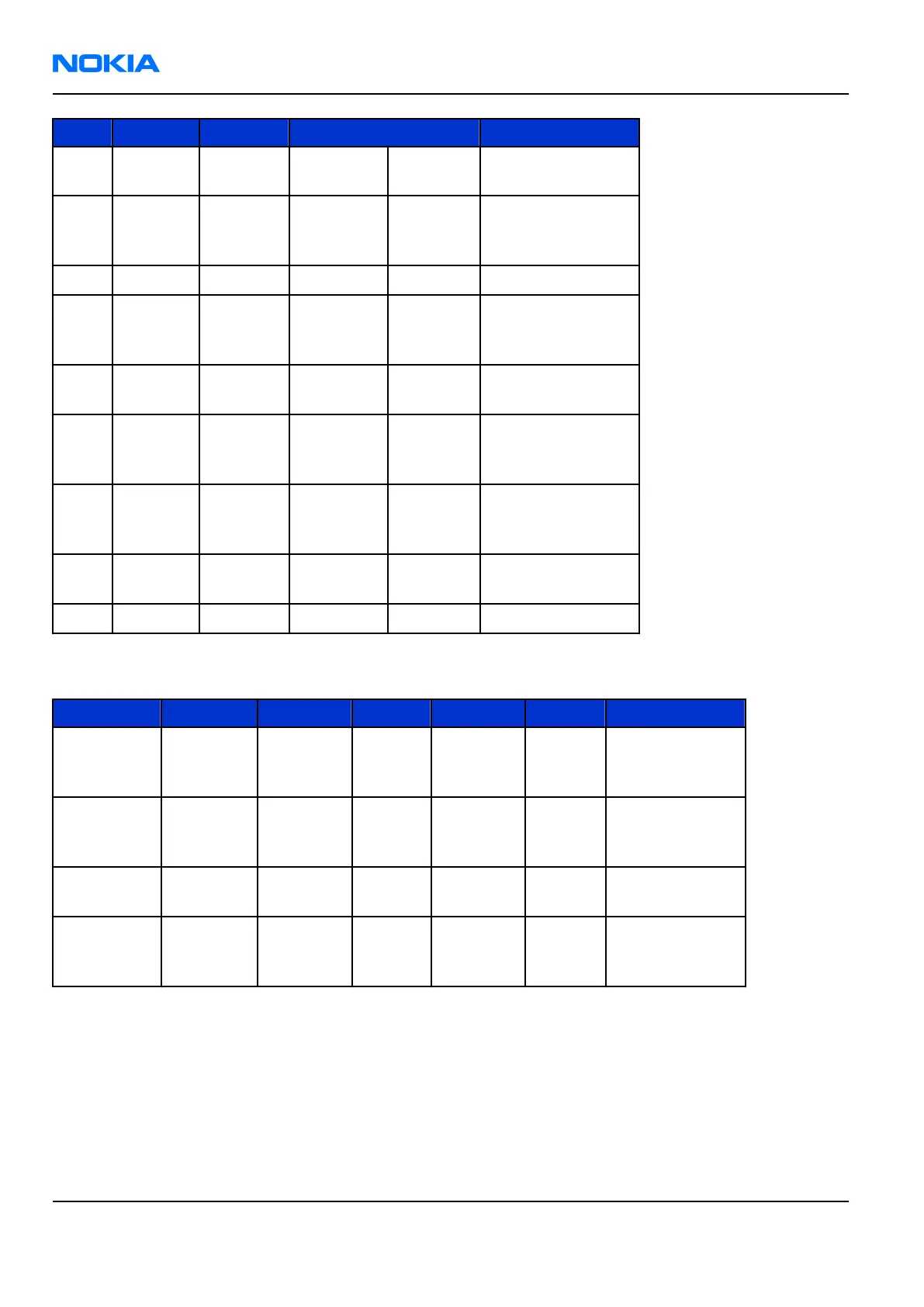
Pin Signal I/O Engine connection Notes
6 CAMCLK <- D4800 ExtClk
System clock for
camera module
7 VDDI <-
N1470
1.8V
regulator VOUT
Camera Digital
Voltage
8 GND
9 CLK+ -> D4800 Ccpclkp
Differential serial
clock, positive
node
10
CAMVCTR
L <- D4800 VCtrl
Camera module
activating signal
11 CLK- -> D4800 Ccpclkn
Differential serial
clock, negative
node
12 VDD <-
N1471
2.8V
Regulator VOUT
Camera analogue
Voltage
13 Strobe ->
No Connect. Signal
Unused.
14 GND
Table 29 Camera CCP IF electrical characteristics
Description Parameter Min Typ Max Unit Notes
Common
mode
voltage
VCMF 0.7 0.75 0.85 V -1
Differential
voltage
swing
VOD 130 185 250 mV -2
Operating
frequency
fCLK 120 160 MHz SW controls
frequency
Differential
rise and fall
time
300 800 ps -3
Note:
• Common mode voltage is a mean value of high and low states of one single-ended signal.
• Differential voltage swing is differential amplitude between signals of differential pair.
• Differential transitions should be only measured with good equipment (bandwidth > 1 GHz),
otherwise results will seem too slow.
RM-180
Nokia Customer Care System Module
Page 9 –42 COMPANY CONFIDENTIAL Issue 1
Copyright © 2006 Nokia. All rights reserved.
 Loading...