Training Guide Course No. 196514
Level 2 Maintenance, X-1000 Series Dispensing Systems 4-110 P/N 196515 (Revision A)
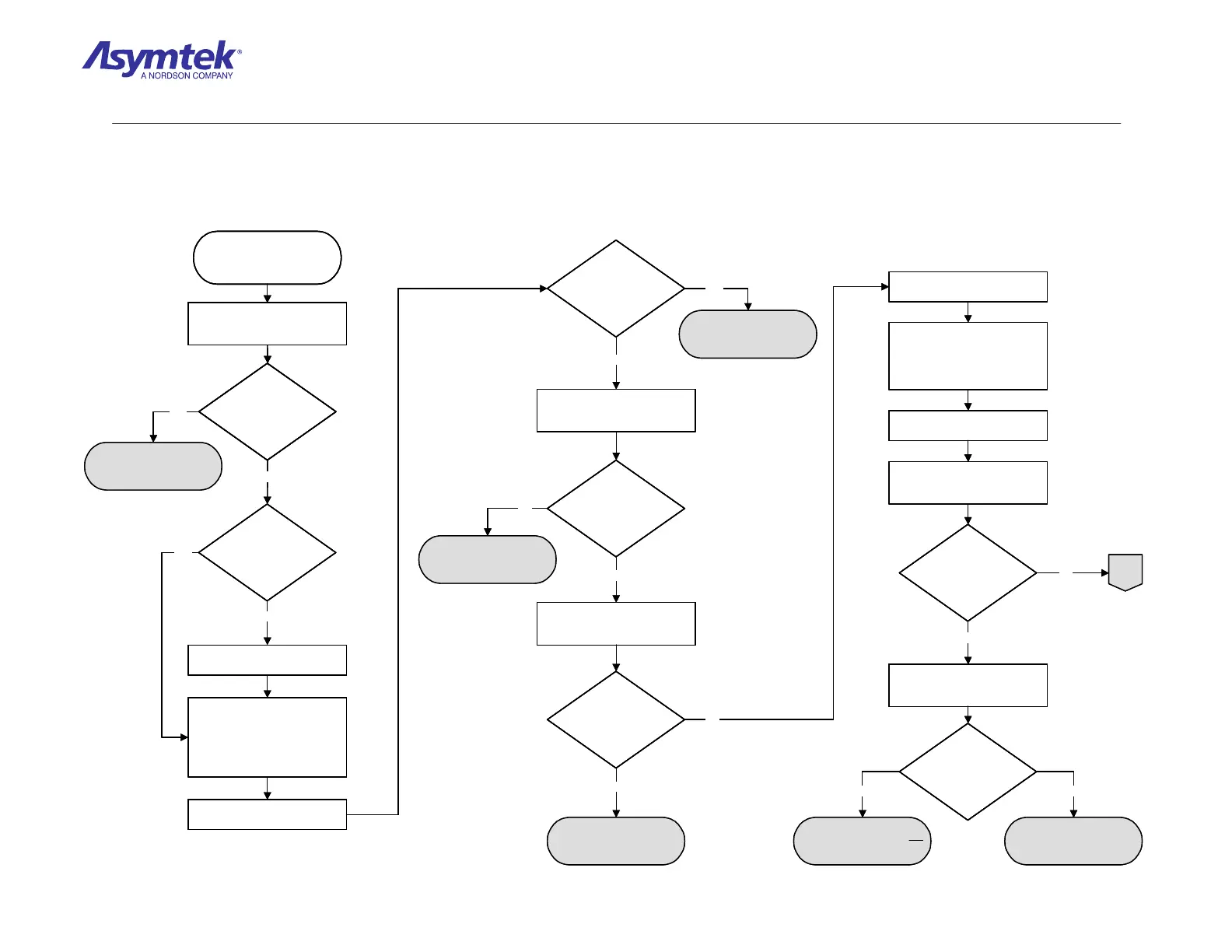
Go to Temperature
Controller Verification
Exit FmNT, shut down Windows
NT, press black OFF (0) button
on the Operator’s Console,
switch Main Circuit Breaker to
OFF (0), and disconnect Power
Cable from the facility outlet.
Check the Thermal Switch on the
bottom of Heater Tooling.
Is the Thermal Switch
in the out position?
Are the Heater Cables
correctly and securely
connected?
Connect the Power Cable
to the facility outlet and
switch Main Circuit Breaker
to ON (I) position,
Are heater elements
generating heat?
Press the green ON (I) button on
the Operator’s Console, and
enter FmNT.
Correct, secure Heater Cable
connections
Measure resistance between
Heater Connector Pin 1 and
Pin 2.
Is resistance
30 ohms for single
element or 60 ohms
for dual element
heater?
Inspect both fuses on each
Heater Channel located on
Temperature Controller panel.
Is the fuse open?
Replace fuse.
Remove side Cover on
Conveyor Controller.
Connect Power Cable to facility
outlet, switch Main Circuit
Breaker to ON (I), press green
ON (I) button on Operator’s
Console, and enter FmNT.
In the FmNT Heater terminal,
turn Heater to ON.
Measure VDC between Terminal
3 and Terminal 4 of the Solid
State Relay.
Does the reading
oscillate between 0
and 5 VDC?
Measure VAC between Terminal
1 and Terminal 2 of the Solid
State Relay.
Heater Tooling has failed
Depressing Thermal
Switch should eliminate
fault. If it reoccurs, contact
Asymtek Tech Support.
A
Yes
No
Yes
No
Yes
No
Yes
No
Yes
No
Yes
No
Does the reading
oscillate between 0
and 208 to 240
VAC?
Heater Tooling Cable has
failed
Stop! Heater Tooling is not
root cause of the fault
Yes No
Go to Temperature
Controller Verification
Exit FmNT, shut down Windows
NT, press black OFF (0) button
on the Operator’s Console,
switch Main Circuit Breaker to
OFF (0), and disconnect Power
Cable from the facility outlet.
Check the Thermal Switch on the
bottom of Heater Tooling.
Is the Thermal Switch
in the out position?
Is the Thermal Switch
in the out position?
Are the Heater Cables
correctly and securely
connected?
Are the Heater Cables
correctly and securely
connected?
Connect the Power Cable
to the facility outlet and
switch Main Circuit Breaker
to ON (I) position,
Are heater elements
generating heat?
Press the green ON (I) button on
the Operator’s Console, and
enter FmNT.
Connect the Power Cable
to the facility outlet and
switch Main Circuit Breaker
to ON (I) position,
Are heater elements
generating heat?
Are heater elements
generating heat?
Press the green ON (I) button on
the Operator’s Console, and
enter FmNT.
Correct, secure Heater Cable
connections
Measure resistance between
Heater Connector Pin 1 and
Pin 2.
Is resistance
30 ohms for single
element or 60 ohms
for dual element
heater?
Is resistance
30 ohms for single
element or 60 ohms
for dual element
heater?
Inspect both fuses on each
Heater Channel located on
Temperature Controller panel.
Is the fuse open?Is the fuse open?
Replace fuse.
Remove side Cover on
Conveyor Controller.
Connect Power Cable to facility
outlet, switch Main Circuit
Breaker to ON (I), press green
ON (I) button on Operator’s
Console, and enter FmNT.
In the FmNT Heater terminal,
turn Heater to ON.
Measure VDC between Terminal
3 and Terminal 4 of the Solid
State Relay.
Does the reading
oscillate between 0
and 5 VDC?
Does the reading
oscillate between 0
and 5 VDC?
Measure VAC between Terminal
1 and Terminal 2 of the Solid
State Relay.
Heater Tooling has failed
Depressing Thermal
Switch should eliminate
fault. If it reoccurs, contact
Asymtek Tech Support.
A
Yes
No
Yes
No
Yes
No
Yes
No
Yes
No
Yes
No
Does the reading
oscillate between 0
and 208 to 240
VAC?
Does the reading
oscillate between 0
and 208 to 240
VAC?
Heater Tooling Cable has
failed
Stop! Heater Tooling is not
root cause of the fault
Yes No
Diagram Sheet 4-8-11
Heater Fault Isolation Procedure – Heater Verification
 Loading...


