Repair
7-9
Part 237478_03
E 2012 Nordson Corporation
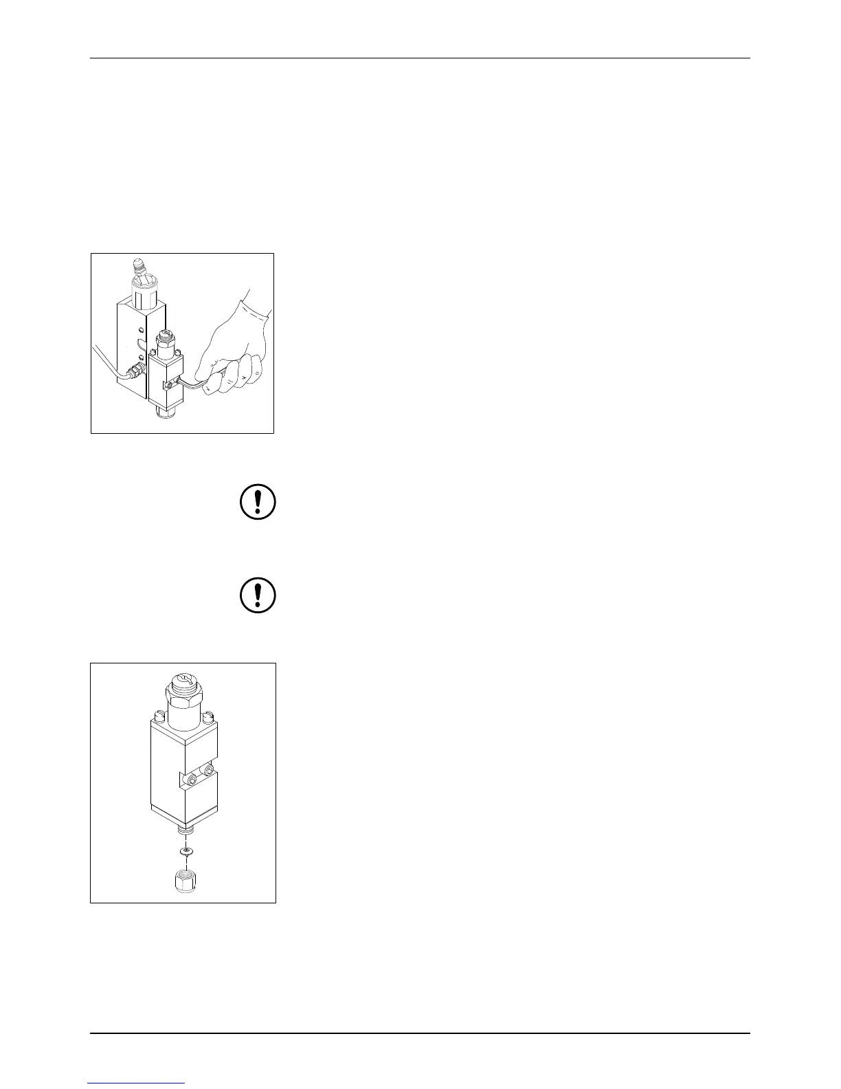
4. Use a hex wrench to remove the two socket‐head screws that secure the
module to the service block, then remove the module.
5. Wipe off any hot melt material left on the service block, especially around
the air passages.
6. Lubricate the new module's o‐rings (refer to Section8, Parts, for
replacement module part numbers).
7.
Ap
ply PTFE paste to the two socket‐head screws.
8. Use the socket‐head screws to secure the new module to the service
block. Torque the screws to 30 in‐lb.
Figure 7‐9 Removing a Module
CAUTION: Do not overtighten. Overtightening can strip the threads.
NOTE: For best results, torque the screws again after the applicator reaches
operating temperature.
CAUTION: Installing swirl nozzles upside down deforms the disk and
prevents the bead from forming a spiral. If a deformed nozzle is then
correctly installed, adhesive may leak into the nozzle air section or an
abnormal pattern may be produced.
9. Reinstall the nozzle and retaining nut. Ensure that swirl nozzles are
correctly placed with the pointed side down. Torque the retaining nut to
20‐25 in‐lb.
10. Restore the system to normal operation by following the instructions in
the applicator product manual.
Figure 7‐10 Installing a Swirl
Nozzle
 Loading...


