Repair
7-17
Part 237478_03
E 2012 Nordson Corporation
1 2 3 4 5
6
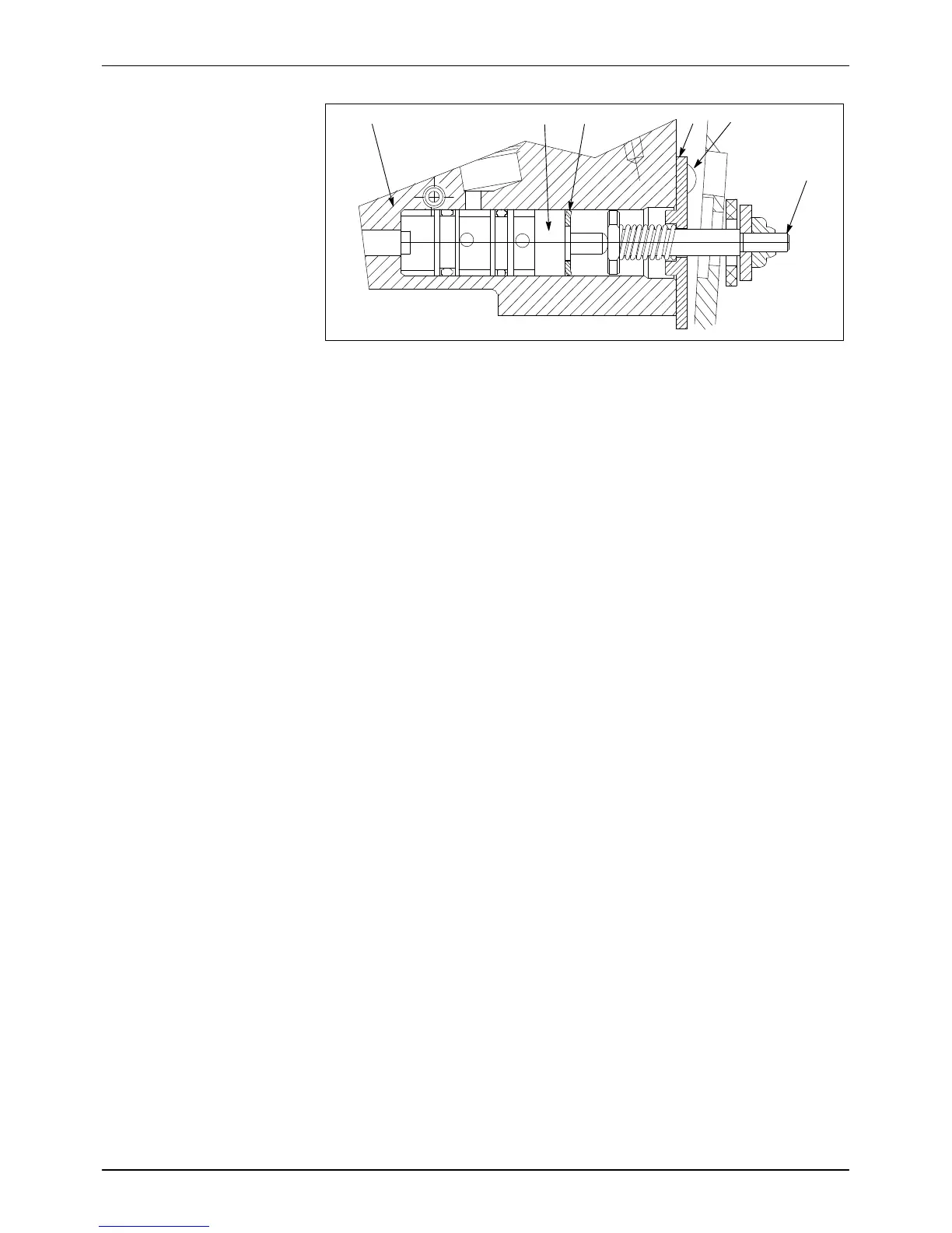
Figure 7‐16 Valve Body Components
1. Valve body
2. Air valve
3. Retaining ring
4. Guide
5. Cap screw
6. Puller
11. Clean the bore to remove any dirt or burrs.
12. Insert the replacement air valve (refer to Section8, Parts, for the air valve
part number).
13. Using a hollow tool (tube), press a new retaining ring into the bore until it
is seated on the air valve.
14. Reattach the trigger, guide and puller.
15. Reconnect the trigger to the valve body.
16. Reassemble the trigger handle as follows:
a. Place the trigger safety inside the trigger (ensure that it is positioned
correctly), then position the valve body, trigger, and trigger safety
inside the right‐hand half of the trigger handle shell (when the gun is
pointing away from you).
NOTE: Be sure that the wave spring is installed on the trigger safety
pivot post.
b. Thread the right‐side shell screw through the top of the shell into the
valve body.
c. Connect the valve body to the outlet air line.
d. Insert the pivot pin through the hole at the top of the trigger and into
the shell.
e. Position the left‐side shell and install all remaining shell screws.
 Loading...


