Installation Checklist
,QVWDOODWLRQ
AFP-300/AFP-400 Installation PN 50253:C1 05/22/97 2-3
Table 2-1 Installation Checklist
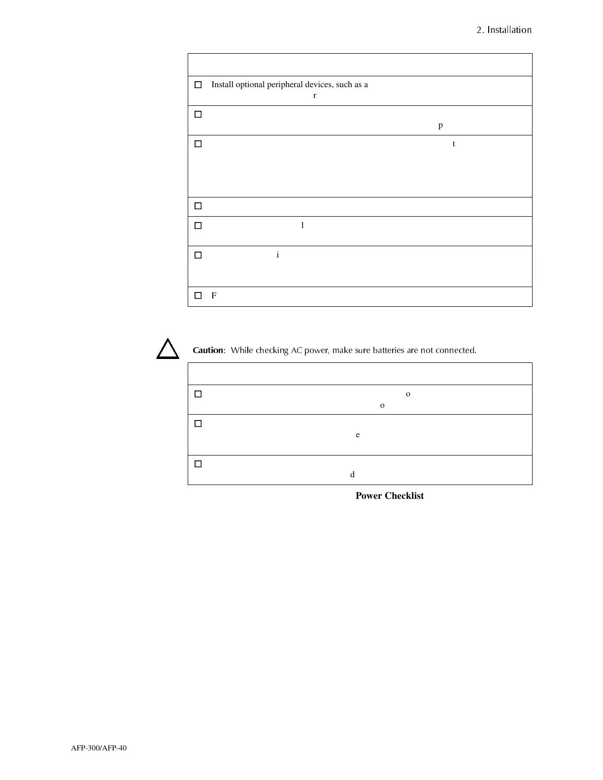
Table 2-2 contains a checklist for checking the system with AC power applied:
&DXWLRQ
:KLOH FKHFNLQJ $& SRZHU PDNH VXUH EDWWHULHV DUH QRW FRQQHFWHG
Table 2-2 AC Power Checklist
Install optional peripheral devices, such as a
printer, personal computer, or CRT-2 terminal.
"Installing Remote Printers and
CRTs" on page 2-35.
Wire the Signaling Line Circuits. "Wiring a Signaling Line Circuit
(SLC)" on page 2-39.
Connect AC power to the MPS-400 — but do not
connect batteries.
"Field Wiring the MPS-400 Power
Supply" on page 2-32
"AC and Battery Power
Connections (MPS-400" on page 2-
33.
Check AC power—but do not connect batteries.* Table 2-2.
Program the control panel. AFP-300/AFP-400 Programming
Manual.
Connect the batteries. "AC and Battery Power
Connections (MPS-400" on page 2-
33.
Field test the system. Section 3.
Component Status
The CPU The green AC Power indicator on; the system Trouble
indicator on because of no battery power.
Each module The yellow Trouble indicator may come on for approximately
10 seconds after applying AC power. (This only applies to an
unconfigured system.)
Each AVPS-24 The yellow Trouble indicator comes on because batteries are
not connected.
Task Refer to...
www.PDF-Zoo.com
 Loading...


