,QVWDOODWLRQ
Wiring a Signaling Line Circuit (SLC)
2-58 AFP-300/AFP-400 Installation PN 50253:C1 05/22/97
6W\OH = 1$& &LUFXLWV
0HWKRG ² 036
SRZHUV &0;
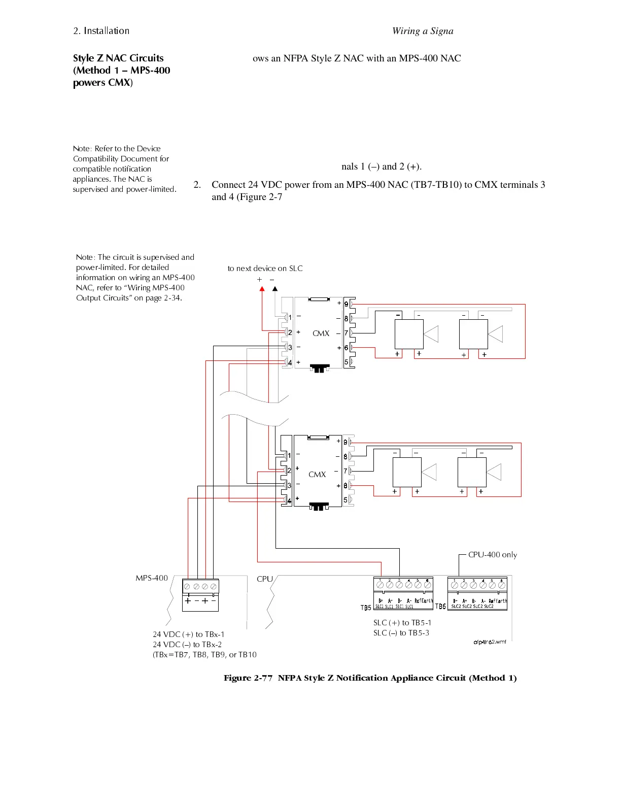
Figure 2-77 shows an NFPA Style Z NAC with an MPS-400 NAC supplying 24 VDC
power to a CMX module. In this circuit, no external ELR is required. When an
MPS-400 NAC supplies power to CMX modules:
• The CMX module outputs are coded if the MPS-400 NAC is coded.
• Program the MPS-400 NAC for general alarm. (Refer to the Programming Manual
for instructions.)
1RWH 5HIHU WR WKH 'HYLFH
&RPSDWLELOLW\ 'RFXPHQW IRU
FRPSDWLEOH QRWLILFDWLRQ
DSSOLDQFHV 7KH 1$& LV
VXSHUYLVHG DQG SRZHUOLPLWHG
Connect the NAC as follows:
1. Connect the SLC to CMX terminals 1 (–) and 2 (+).
2. Connect 24 VDC power from an MPS-400 NAC (TB7-TB10) to CMX terminals 3
and 4 (Figure 2-77).
3. Set the CMX rotary switches to the required loop address. (The CMX takes one
module address on the SLC.) For instructions on setting rotary switches, see
Figure 2-68 on page 2-49.
)LJXUH 1)3$ 6W\OH = 1RWLILFDWLRQ $SSOLDQFH &LUFXLW 0HWKRG
6/& WR 7%
6/& ² WR 7%
&38 RQO\
9'& WR 7%[
9'& ² WR 7%[
7%[ 7% 7% 7% RU 7%
WR QH[W GHYLFH RQ 6/&
²
1RWH 7KH FLUFXLW LV VXSHUYLVHG DQG
SRZHUOLPLWHG )RU GHWDLOHG
LQIRUPDWLRQ RQ ZLULQJ DQ 036
1$& UHIHU WR ´:LULQJ 036
2XWSXW &LUFXLWVµ RQ SDJH
&0;
&0;
036
&38
www.PDF-Zoo.com
 Loading...


