IFS-2600 Fire Indicator Panel Section 4 Installation
DOC-01-009 29
IFS-2600 MIMIC
MIMIC Outputs:
A mimic output is standard on all IFS-2600 panels. This output mimics the status of all alarm zones fitted
on the panel to a remote mimic panel in the building.
The four (4) wire serial mimic decoder board can be connected to the panel by using a 4-core cable. 4
conductors are used, 24VDC, 0V, data, & clock connecting directly to their respective terminals at the
panel and the mimic.
The decoder boards contain up to 64 alarm LED indicators, 64 fault LED indicators, a sounder, sounder
mute, lamp test facility and conventional mimic outputs at the rear of the board for interfacing to
conventional mimic panels or driving auxiliary relay outputs up to a maximum of 20mA.
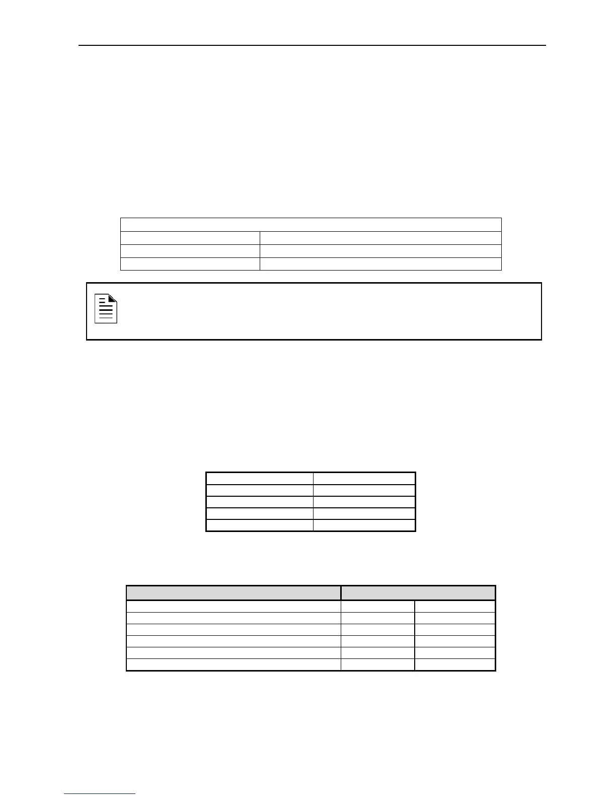
Maximum Number of Mimics
7
Cable used for Connection
0.75mm, 4-core for Power & Serial Data Connections
Maximum Length of Cable
120 Metres
Printer Output
The printer port is designed to be used during testing and commissioning of the panel. The serial printer
will report alarms and faults together with the date and time of the event. The printer can also be used
during “walk test” mode to produce a history of the test and can also be used to print current programming
configuration.
A DB9 plug male is provided at the top of the main termination board. This communication port will
communicate with an IBM compatible serial printer (ASCII printer) with the following settings.
Baud Rate 1200 bps
Data Bits 8
Stop Bits 1
Parity None
Handshaking DTR
Cabling to the printer requires a 4-core telephone style cable with a maximum length of 10 metres. A DB9
socket is required at the panel end. The printer end is dependent on the type of printer used but is usually
a male DB25. Connection is as follows. A 5-core cable can be used for both comms and printer functions
2 RX (only for programming) 2 3
3 TX 3 2
5 GND 7 5
7 RTS ( do not use) (5) (8)
8 CTS ( only for printer) 4 7
Table 4-6, Cable connection
NOTE:
Refer to IFS-2600 Equipment Overview (Section 4.3) & MIMIC Connection Diagram
(Section 6.4.5) for more details about connecting a mimic to the standard IFS-2600
panel.