IFS-2600 Fire Indicator Panel Section 4 Installation
DOC-01-009 30
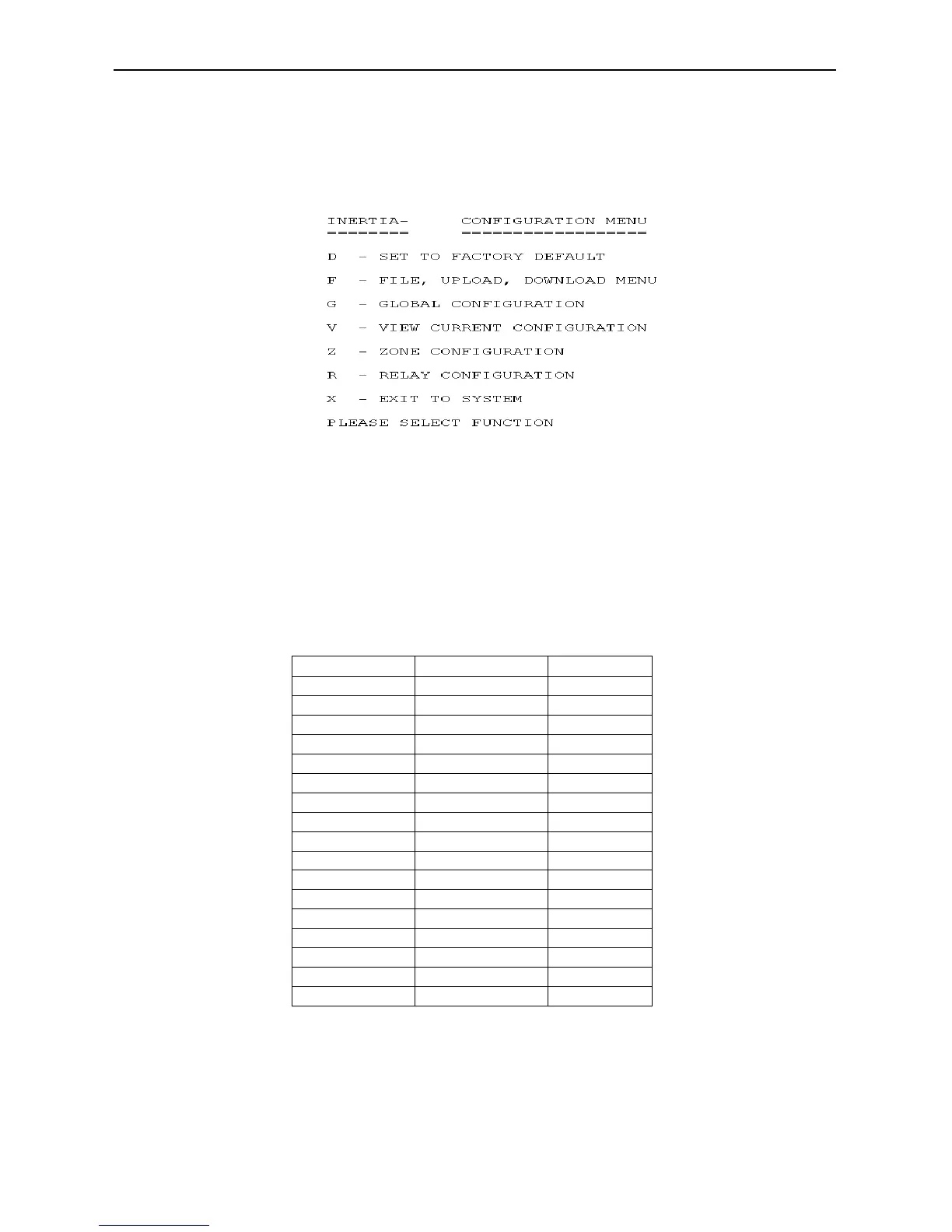
Programming By Computer
Programming of the zones, relays, global functions and time can be set with the DOS based program
“2600/SW” using the printer port (Cannot be used with Windows XP).
After the cable is installed, the program can be run and the menu will prompt for the available functions.
Alarm Threshold Comparator TP7 (For IFS-2005 & IFS-2006 Boards Only)
With the panel in the quiescent mode, measure and take note of the INTERNAL 24V DC POWER SUPPLY
as above.
Measure the voltage between system 0V and TP7. Adjust multi-turn potentiometer VR4, and adjust until
the voltage is as per the following table.
20.6 2.833 2.80 to 2.86
21.0 2.888 2.86 to 2.92
21.5 2.956 2.93 to 2.99
22.0 3.025 2.99 to 3.06
22.5 3.094 3.06 to 3.12
23.0 3.163 3.13 to 3.19
23.5 3.231 3.20 to 3.26
24.0 3.300 3.27 to 3.33
24.5 3.369 3.34 to 3.40
25.0 3.438 3.40 to 3.47
25.5 3.506 3.47 to 3.54
26.0 3.575 3.54 to 3.61
26.5 3.644 3.61 to 3.68
27.0 3.713 3.68 to 3.75
27.5 3.781 3.74 to 3.82
27.6 3.795 3.76 to 3.83
28.0 3.850 3.81 to 3.89
Table 4-7, Voltage Adjustments (Alarm)
2600
Figure 4-8, Programming Options