IFS-2600 Fire Indicator Panel Section 4 Installation
DOC-01-009 31
Fault Threshold Comparator TP6 (For IFS-2005 & IFS-2006 Boards Only)
With the panel in the quiescent mode, measure and take note of the INTERNAL 24V DC POWER SUPPLY
as above.
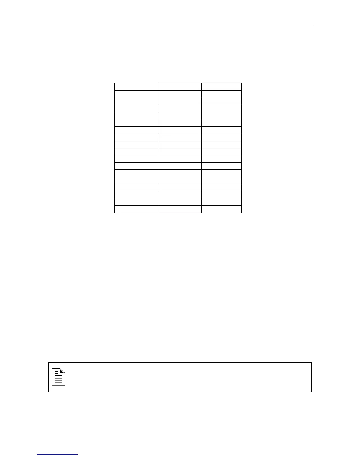
Measure the voltage between system 0V and TP6. Adjust multi-turn potentiometer VR1, and adjust until
the voltage is as per the following table.
20.6 0.600 0.59 to 0.61
21.0 0.612 0.61 to 0.62
21.5 0.626 0.62 to 0.63
22.0 0.641 0.63 to 0.65
22.5 0.655 0.65 to 0.66
23.0 0.670 0.66 to 0.68
23.5 0.684 0.68 to 0.69
24.0 0.699 0.69 to 0.71
24.5 0.714 0.71 to 0.72
25.0 0.728 0.72 to 0.74
25.5 0.743 0.74 to 0.75
26.0 0.757 0.75 to 0.76
26.5 0.772 0.76 to 0.78
27.0 0.786 0.78 to 0.79
27.5 0.801 0.79 to 0.81
27.6 0.804 0.80 to 0.81
28.0 0.816 0.81 to 0.82
Table 4-8, Voltage Adjustments (Fault)
Configuration Jumpers
IFS-2004 - JP3 CPU Default
Holding a short across these pins for 5 seconds during start-up causes the panel to reset to standard
factory defaults. The panel will give 4 beeps after reset, to acknowledge default on start-up.
IFS-2004 - JP4 CPU Program Disable
When fitted, jumper between these pins to inhibit program changes.
IFS-2004 - JP5 CPU Reset
With panel operating, a momentary short across these pins will cause a CPU restart.
IFS-2005 & NI-2025-01 – JP2 DOOR HOLDER BYPASS
If zoned door holder outputs are required and is to be done external to the main termination board, then
the main door holder release needs to be disabled. Fitting a link across JP2 on IFS2005 PCB does this.
NOTE:
Door holder output is only enabled if optional door holder transformer is fitted. SW1
must be linked on IFS-2004 CPU board prior to Version 6 Firmware.