18
BA_v2_eagle_parallel_EN_1-0
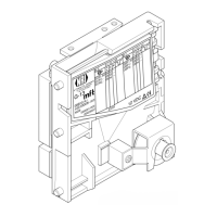
Design
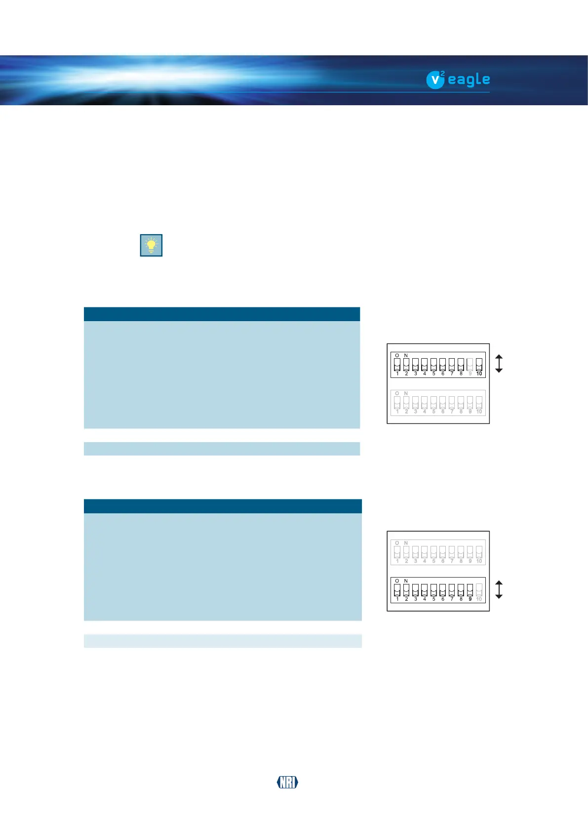
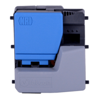
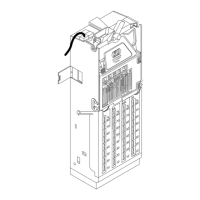
4.5 Switch blocks
The coin validator has two switch blocks [Fig. 1/13] [Fig. 2/14] with ten DIL switches each
(S1.1-10 and S2.1–10) on the rear of the device. The DIL switches can be used to set certain
device functions:
Tondouthowtosettheindividualfunctionswiththehelpoftheswitchblock,referto
Chap. 7
Operation, p. 34
On the rear of the device you will nd a brief description of the individual switch
functions.
4.5.1 Switch functions – switch block S1
DIL switch Function
OFF ON
S1.1 Coin channel 1 accepts inhibited
S1.2 Coin channel 2 accepts inhibited
S1.3 Coin channel 3 accepts inhibited
S1.4 Coin channel 4 accepts inhibited
S1.5 Coin channel 5 accepts inhibited
S1.6 Coin channel 6 accepts inhibited
S1.7 Coin channel 7 accepts inhibited
S1.8 Coin channel 8 accepts inhibited
S1.9 not used – –
S1.10 Memory block A B
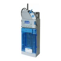
4.5.2 Switch functions – switch block S2
DIL switch Function
OFF ON
S2.1 Coin channel 9 accepts inhibited
S2.2 Coin channel 10 accepts inhibited
S2.3 Coin channel 11 accepts inhibited
S2.4 Coin channel 12 accepts inhibited
S2.5 Coin channel 13 accepts inhibited
S2.6 Coin channel 14 accepts inhibited
S2.7 Coin channel 15 accepts inhibited
S2.8 Coin channel 16 accepts inhibited
S2.9 Operating mode normal mode teach mode
S2.10 not used – –
ON
OFF
ON
OFF