Page: 19
Service Guide ML395/395C
Chapter 2 Principles of Operation
2.1.06 Spacing Drive Circuit
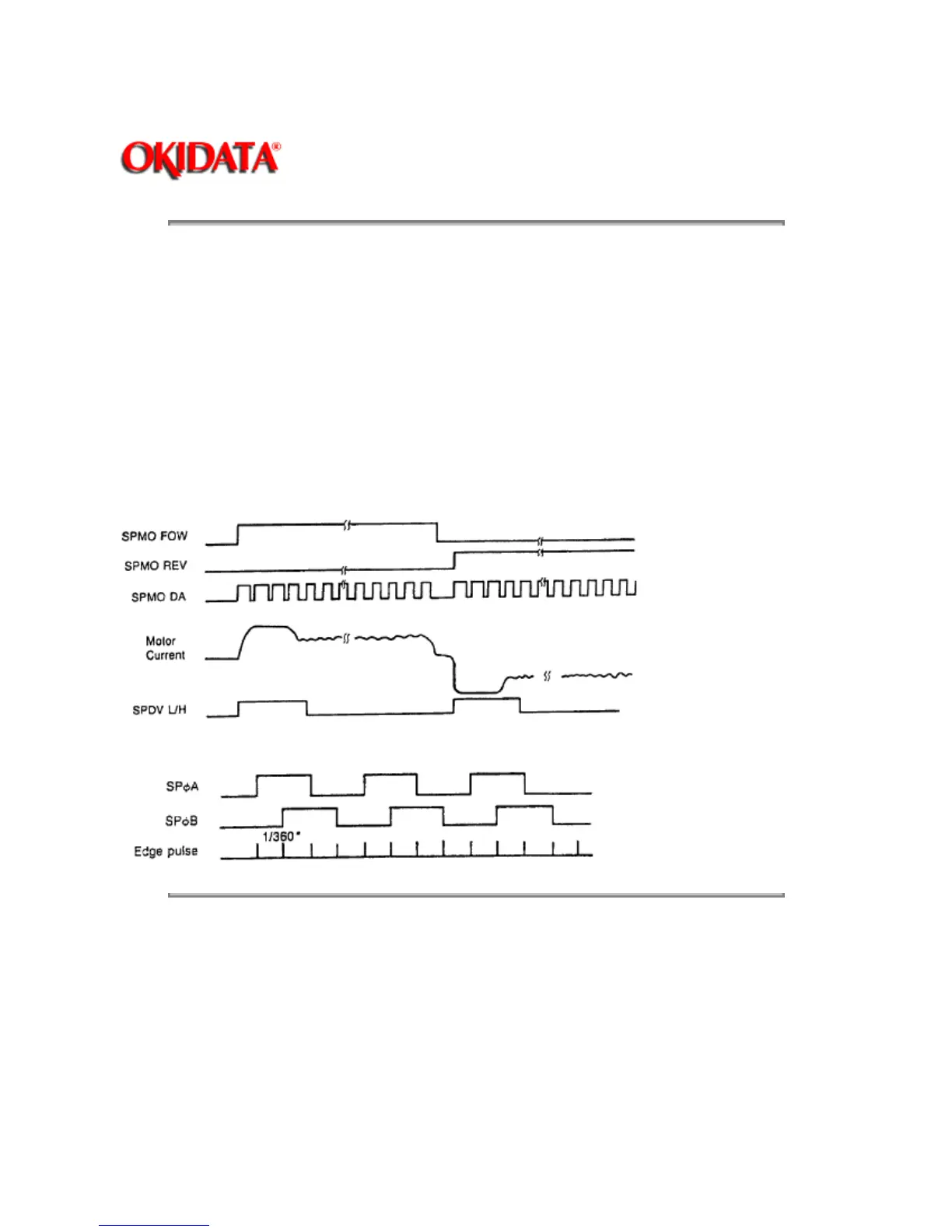
The Motor Control LSI (Q9) outputs the SPMO DA signal upon receiving the spacing command from the
Slave MPU (Q11). This is a fixed cycle pulse signal.
To control the motor speed, the Motor Control LSI varies the pulse duty cycle according to the speed data
from the Slave MPU.
The SPMO FOW or SPMO REV signal from the Head Control LSI (Q8) changes the current direction in
the DC motor to run the motor in either the forward or reverse direction.
As the space motor rotates, it generates feedback pulse signals SPfA and SPfB. The Motor Control LSI
detects the edge pulses from these signals and divides the frequency to output the MO
LSI IPT signal for use in Dot Timing.
Copyright 1997, Okidata, Division of OKI America, Inc. All rights reserved. See the OKIDATA Business
Partner Exchange (BPX) for any updates to this material. (http://bpx.okidata.com)
 Loading...