18
Chapter 2 Instrument Nomenclature
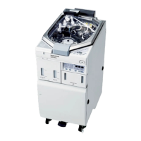
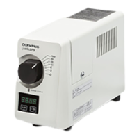
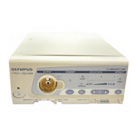
VISERA XENON LIGHT SOURCE CLV-S40
1. VIDEO IN connector
When the video system is connected, the brightness can be automatically
controlled by the video signals from the video system.
2. SYSTEM connector
The connector accepts connection from an external unit for control of
brightness and other settings.
3. VIDEO OUT connector
The connector passes the video signal to the monitor.
4. AC inlet
The inlet accepts the AC power cord.
5. Circuit breakers
The breakers shut down the power supply when higher current than rated
flows through the equipment.
6. LIGHT CONT. connector
The connector is used for automatic brightness control when connected to
an Olympus OTV-S5, OTV-S6, OTV-S7V, OTV-SX or OTV-SX2 video
system.
7. Equipotential terminal
In the case of equipotential, connect this terminal to a potential equalization
busbar of the electrical installation.
8. Lamp access cover
The cover is opened to allow replacement of the main lamp (xenon).
9. Cover
The cover is removed to allow attachment of the connector cover holder.
10. Side bumpers
The bumpers prevent the air vents from being obstructed. They also prevent
the light source from being placed on its side.
 Loading...