CMC 356 Reference Manual
72
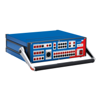
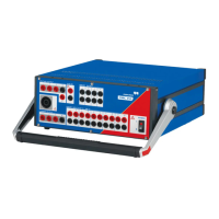
Using the CMC 356 test set in combination with the Test Universe module
Transducer enables advanced testing of multifunctional single-phase and
three-phase electrical transducers with symmetrical or non-symmetrical
operating characteristics.
The hardware option ELT-1 can either be ordered with the new test set or
later as a factory upgrade (the CMC 356 needs to be returned to
OMICRON).
6.11.1 General Data
The actual capturing of the measurement values and the range switching for
the channels takes place in the analog input stages AFE (A
nalog Front
E
nd). Each AFE is used by two input channels and galvanically separated
from the other input stages.
The measured values are passed through an isolation amplifier to the
"Measurement Unit" and digitized by an A/D converter. The further
processing is done by a high-performance floating point digital signal
processor (DSP).
As such, apparent power, reactive power, active power, etc., can be
provided in real-time and transmitted to the PC.
The analog measurement inputs have five measurement ranges that can be
configured individually in the test module EnerLyzer.
• 100 mV
•1V
•10V
• 100 V
• 600 V
These range limits refer to the respective rms values of sinusoidal input
signals. The ranges 100 mV, 1 V, 10 V and 100 V can be overloaded
approximately with 10 %.
Input impedance: 500 kOhm || 50 pF for all measurement ranges.
Overload protection: 600 Vrms (± 850 Vpeak) from reference potential N,
from another input, or protective earth (GND).
The sampling rate can be configured by software:
• 28.44 kHz
•9.48kHz
•3.16kHz