Sinusoidal
encoder in-
put
*3
Input form Line receiver input + AD conversion
Number of inputs 2 points/channel (SIN signal, COS signal)
Maximum rated input voltage 0 to Encoder Power Supply (+5 V)
Encoder Power Supply as GND reference
Allowable differential input
voltage range
0.6 to 1.35 Vpp
Allowable input voltage range 0 to 4.0 V
Encoder Power Supply as GND reference
Maximum input frequency 2 MHz
AD converter resolution 16 bits
Maximum cable length 20 m
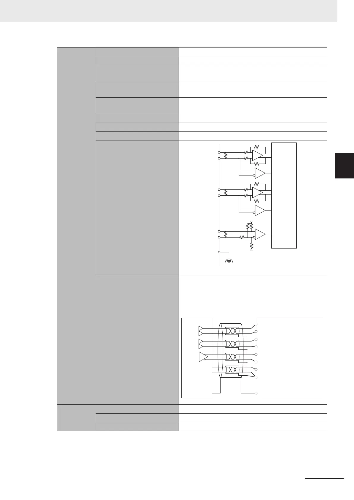
Circuit configuration
120 Ω
SIN+
+
-
SIN-
120 Ω
COS+
+5 V
+
-
COS-
120 Ω
3.3 kΩ
330 Ω
3.3 kΩ
2.2 kΩ
INDEX+
INDEX-
Connector shell
Internal
circuit
F
G
0 V
Terminal connection diagram To reduce the effects of the noise, we recommend that you
use a double-shielded cable and connect the inner shields
to the Encoder Power Supply (GND) pin and the outer
shield to the connector shell.
Connector shell
Encoder Power Supply (GND)
Encoder Power Supply (+5 V)
Encoder
INDEX-
INDEX+
COS-
COS+
SIN-
SIN+
+5 V
INDEX
COS-
COS+
SIN-
SIN+
0 V
+
-
+
-
+
-
Digital Hall
sensor
*4
ON Voltage 3.0 VDC min.
OFF Voltage 0.9 VDC max.
Maximum input rating -0.3 to 6.0 VDC
3 Configuration Units
3-19
CK3M-series Programmable Multi-Axis Controller User's Manual Hardware (O036)
3-3 Axis Interface Unit
3
3-3-5 Encoder Connector Specifications

 Loading...


