Circuit configura-
tion
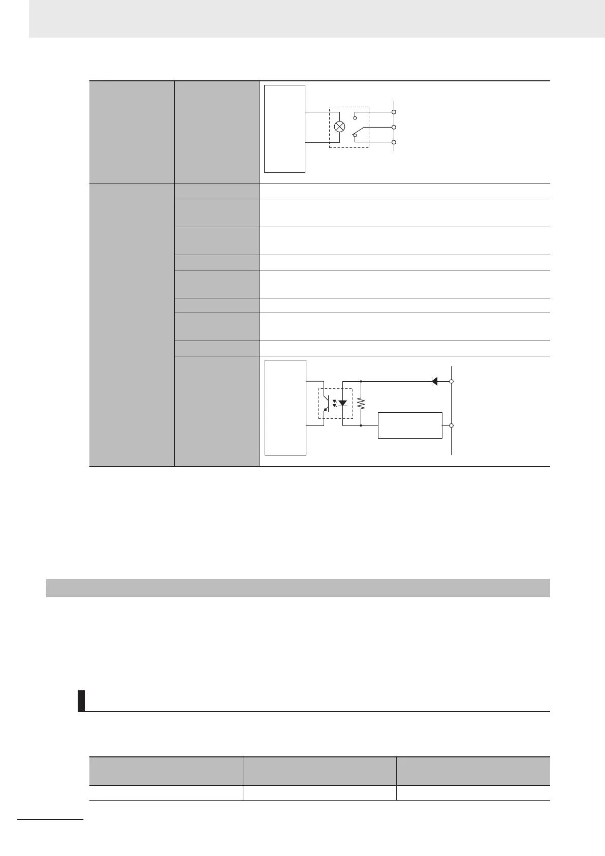
Internal
ci
rcuit
Amp enable NO
Amp enable common
Amp enable NC
Fault input
*2
Number of inputs 1 point/channel
Rated input volt-
age
5 to 24 VDC
Maximum input
voltage
26.4 VDC
Input current 7 mA typical (24 VDC)
ON voltage/ON
current
3 VDC min./1 mA min.
OFF current 0.1 mA max.
ON/OFF re-
sponse time
20 μs min./400 μs max.
Isolation method Isolation by Photocoupler (between fault input and internal circuit)
Circuit configura-
tion
Fault input +
Internal
circuit
Fault input -
Current
control circuit
*1. In DACA-, the reversed voltage of the DACA+ is output. In other words, when DACA+ = +10 V, then DACA-
= -10 V
. In this case, between DACA+ and DACA-, a 20 V potential difference is generated. The same ap-
plies to DACB+/DACB-.
*2.
Available with the CK3W-AX1414£/1515£ Units.
*3.
For connection with a Servo Drive with 5-VDC photocoupler input, only CK3W-AX1414£/-AX1515£ Units
whose date of production is July 1, 2019 or later (Lot number 01719K and later) are available.
Refer to A-6 How to Read the Lot Number on page
A-11 for the lot number.
3-3-11
DA Output Method
The following two methods are available for DA output.
•
FilteredPWM
• TrueDAC
This section describes each of the methods.
FilteredPWM
This is a method for creating analog output by smoothing the PWM pulse.
The relationship between the set value and output voltage is shown below
.
Set value
Voltage between analog output +
and analog output -
Voltage between analog output +
and analog GND
-16384 -20 V -10 V
3 Configuration Units
3-30
CK3M-series Programmable Multi-Axis Controller User's Manual Hardware (O036)

 Loading...


