6-2
Using the Indicators to Check Errors
6-2-1
Indicator Types
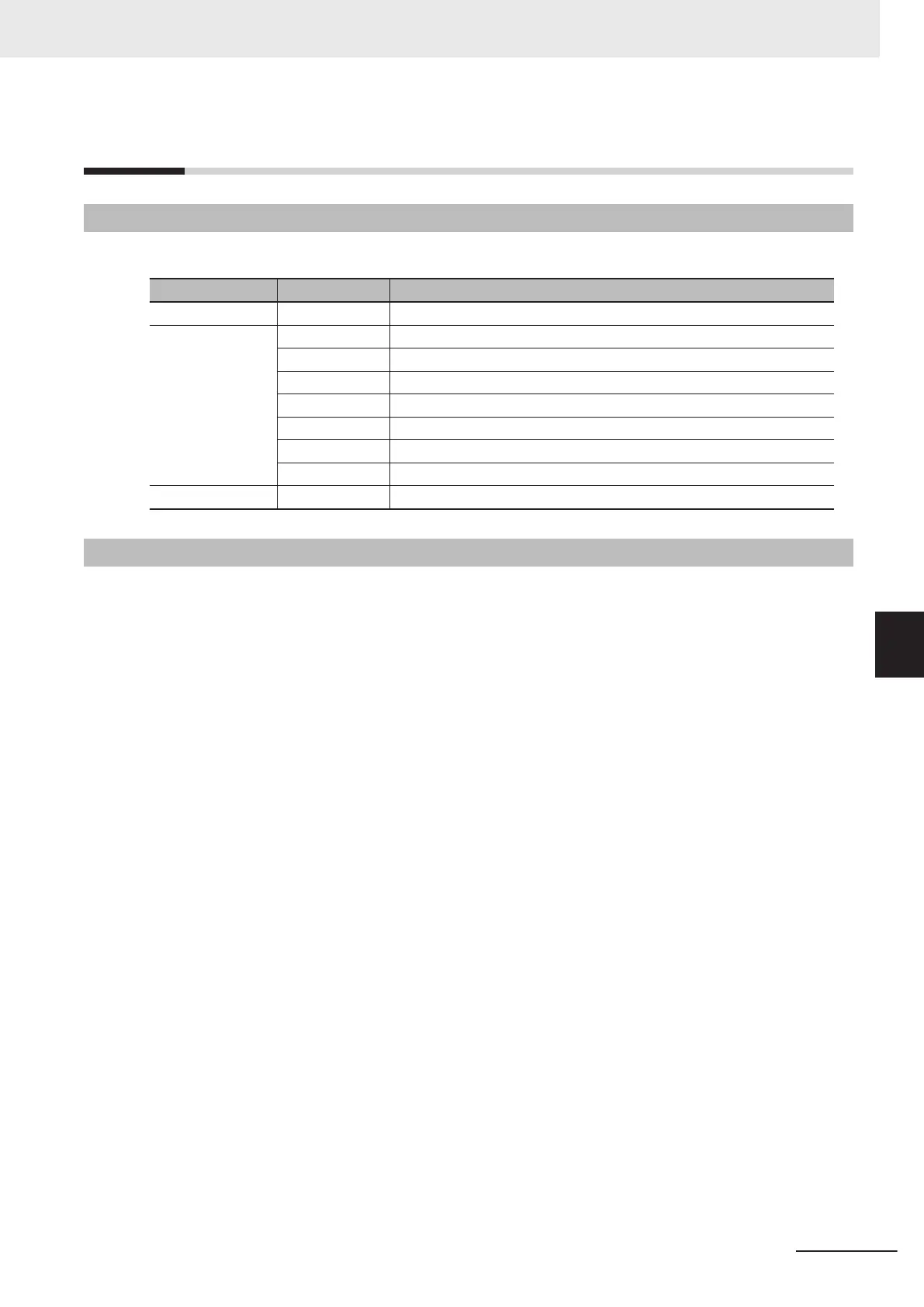
The Motion Controller indicators used for error checks and their functions are as shown below.
Unit Indicator name Description
Power Supply Unit PWR Shows that power is being supplied to the Unit.
CPU Unit PWR Shows the CPU Unit internal power status.
RDY Shows whether the CPU Unit is in operation-ready status.
ERR Shows the CPU Unit watchdog timer error status.
ECAT LINK Shows the link status of EtherCAT communications.
ECAT ACT Shows the data communications status of EtherCAT communications.
Ethernet LINK Shows the link status of Ethernet communications.
Ethernet ACT Shows the data communications status of Ethernet communications.
CK3W Unit PWR Shows the Unit internal power status.
6-2-2
Procedure for Identifying Errors
When an error occurs in the Motion Controller, check the indicators with the following flowchart to first
identify if either a "non-fatal error in the CPU Unit" or a "fatal error in the CPU Unit" has occurred.
6 Troubleshooting
6-3
CK3M-series Programmable Multi-Axis Controller User's Manual Hardware (O036)
6-2 Using the Indicators to Check Errors
6
6-2-1 Indicator Types

 Loading...


