One CK3W Unit in the system supplies servo clock and phase clock signals to all the other Units.
The supply-source CK3W Unit must be installed to the CPU Rack.
Connect the Unit with the smallest address value to the CPU Rack because, by default, it is the supply
source of clock signals.
Y
ou may specify the Unit with a desired address as the clock supply source by setting the register.
If the Unit that serves as the clock supply source is connected to the Expansion Rack, an error occurs
because the CPU Unit cannot recognize clock signals.
If this error occurs, the Sys.Status register Sys.NoClocks becomes 1.
3-4-5
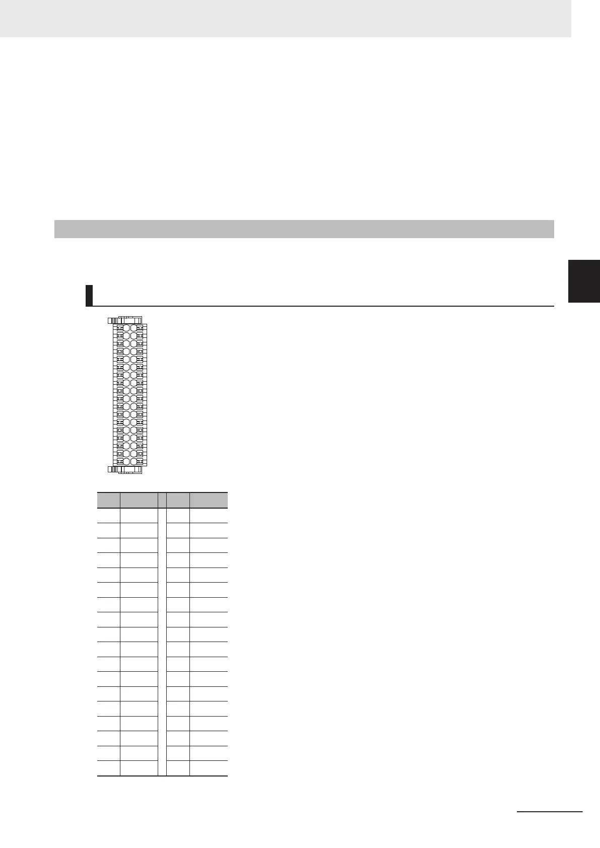
Terminal Arrangement
This section describes the terminal arrangement of the digital I/O connection terminal block.
CK3W-MD7110
No. Signal No. Signal
1 IN00 19 IN08
2 IN01 20 IN09
3 IN02 21 IN10
4 IN03 22 IN11
5 IN04 23 IN12
6 IN05 24 IN13
7 IN06 25 IN14
8 IN07 26 IN15
9 V1 27 V1
10 OUT00 28 OUT08
11 OUT01 29 OUT09
12 OUT02 30 OUT10
13 OUT03 31 OUT11
14 OUT04 32 OUT12
15 OUT05 33 OUT13
16 OUT06 34 OUT14
17 OUT07 35 OUT15
18 V2 36 G2
3 Configuration Units
3-49
CK3M-series Programmable Multi-Axis Controller User's Manual Hardware (O036)
3-4 Digital I/O Unit
3
3-4-5 Terminal Arrangement
 Loading...


