Connect the Unit with the smallest address value to the CPU Rack because, by default, it is the supply
source of clock signals.
Y
ou may specify the Unit with a desired address as the clock supply source by setting the register.
If the Unit that serves as the clock supply source is connected to the Expansion Rack, an error occurs
because the CPU Unit cannot recognize clock signals.
If this error occurs, the Sys.Status register Sys.NoClocks becomes 1.
3-5-5
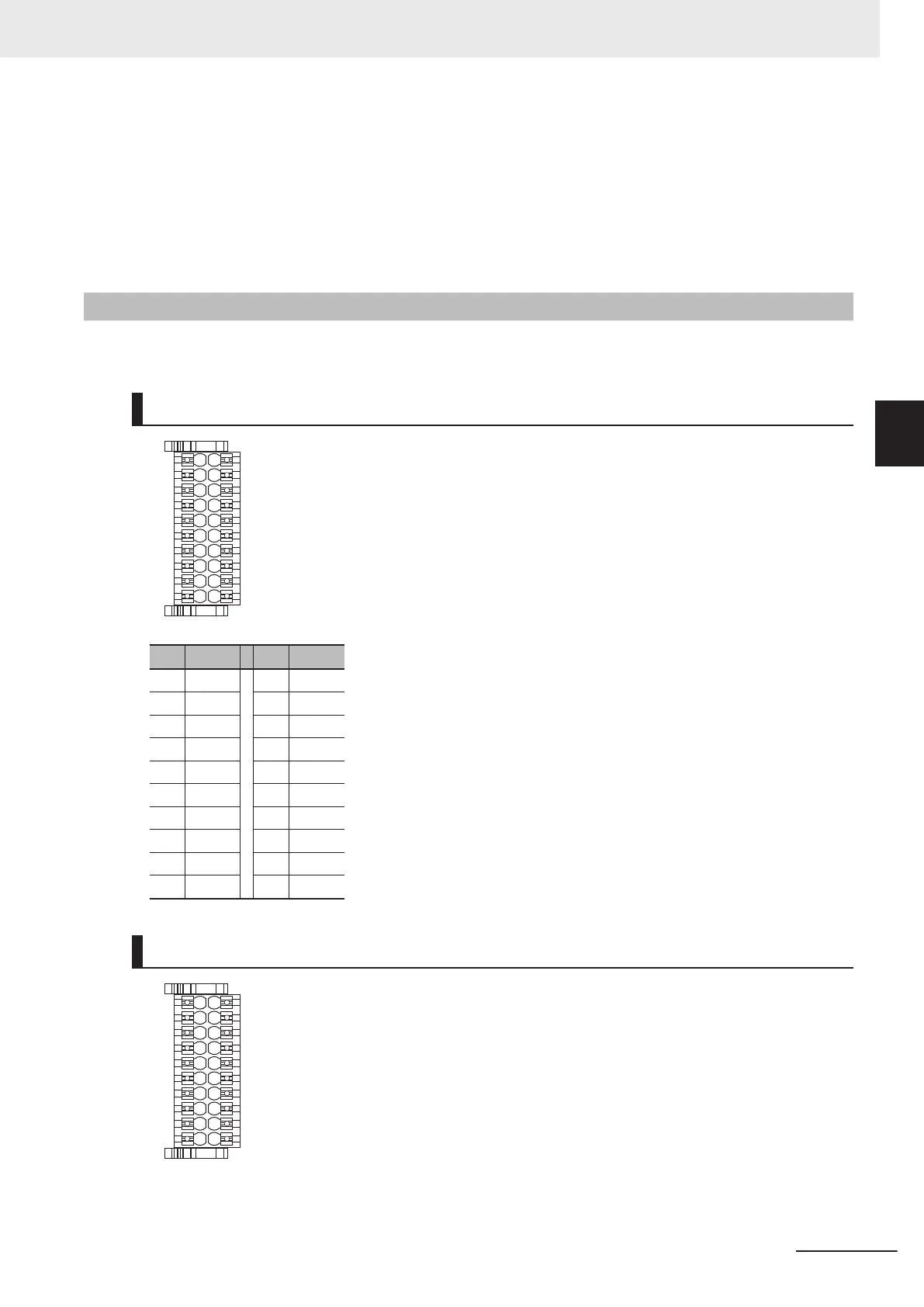
Terminal Arrangement
This section describes the terminal arrangement of the analog input connection terminal block.
CK3W-AD2100
No. Signal No. Signal
1 AIN0+ 11 AIN0-
2 AIN1+ 12 AIN1-
3 AIN2+ 13 AIN2-
4 AIN3+ 14 AIN3-
5 AGND 15 AGND
6 NC 16 NC
7 NC 17 NC
8 NC 18 NC
9 NC 19 NC
10 AGND 20 AGND
CK3W-AD3100
3 Configuration Units
3-55
CK3M-series Programmable Multi-Axis Controller User's Manual Hardware (O036)
3-5 Analog Input Unit
3
3-5-5 Terminal Arrangement
 Loading...


