Single-Ended Input
C
G
B
Phase A/
Phase B
ON
OFF
ON
OFF
OFF
Voltage
OFF
Voltage
ON
ON
Vol-
tage
Vol-
tage
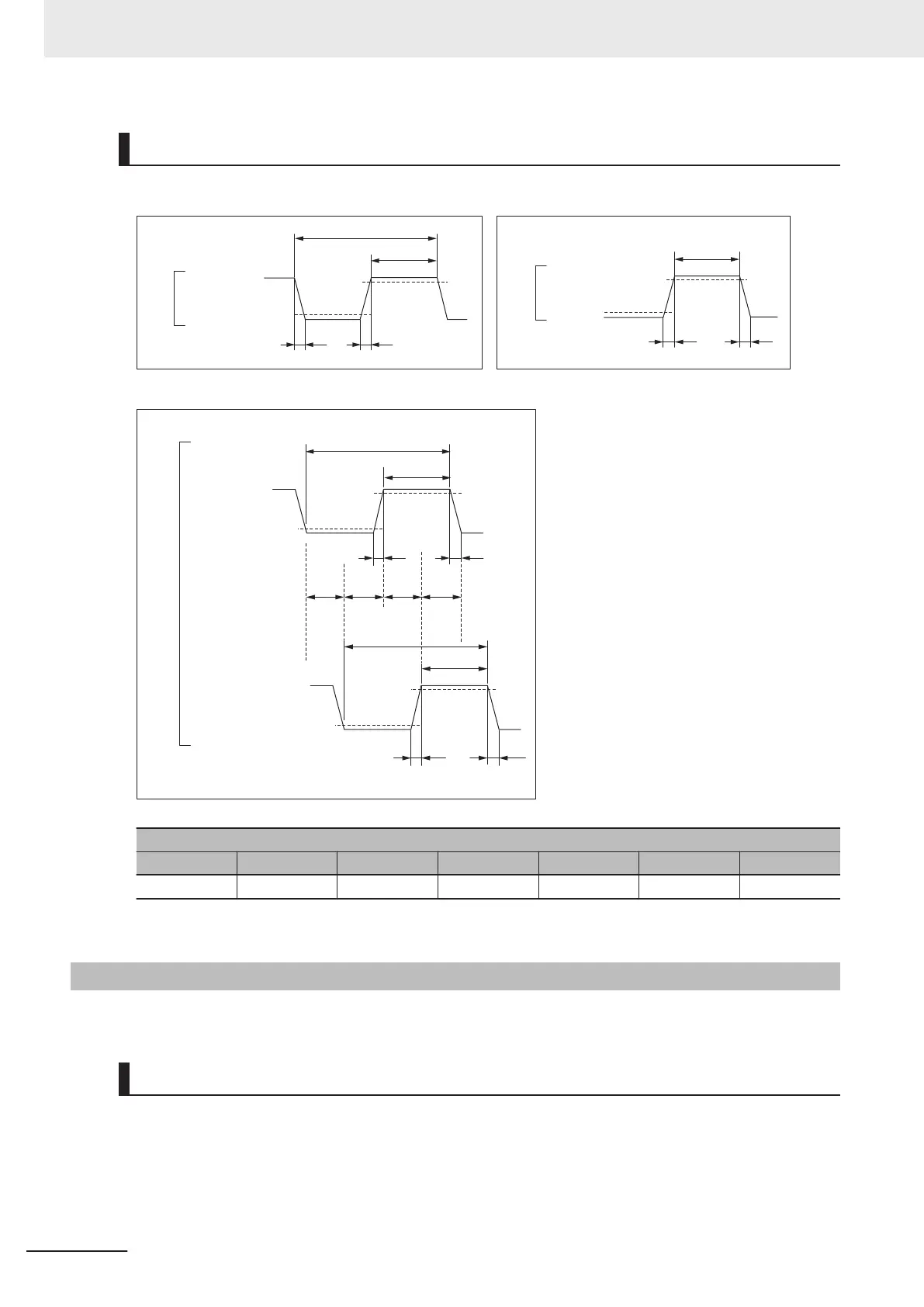
Encoder input (Phases A & B)
Input pulse duty = 50%
Encoder input (Phase C)
Ter-
minal
Input
Ter-
minal
Input
Phase C
Ter-
minal
Input
D
E
ON
A A
AA
FFFF
Voltage
OFF
Voltage
OFF
Voltage
Relationship between Phase A and Phase B for Phase Differential Pulse Inputs
Phase A
Phase B
E
D
ON
A A
A A
Vol-
tage
Timing conditions (with 10 MHz input)
A B C D E F G
< 2.5 ns > 50 ns > 100 ns > 50 ns > 100 ns > 25 ns > 50 ns
(With Gate3[i].EncClockDiv = 0: 100MHz setting)
3-3-8
Input Specifications for Sinusoidal Encoder
This section describes the input specifications for the sinusoidal encoder.
Input Waveform
For the sinusoidal encoder, input a sinusoidal differential signal with an amplitude of 1 Vpp between
SIN+ and SIN-.
With GND as the reference voltage, the SIN+ waveform has an amplitude of 0.5 Vpp with the center
line at approximately 2.5 V
, whereas the waveform is inverted for SIN-.
3 Configuration Units
3-24
CK3M-series Programmable Multi-Axis Controller User's Manual Hardware (O036)
 Loading...


