Connection diagram
Connector shell
O
utFlagB
GND
For the GND, use an encoder power source (GND).
*1.
This function is available with the CK3W-AX1313£/-AX1414£/-AX1515£ Units.
*2. With single-ended input, only a voltage output type encoder can be connected. Open collector type encod-
ers cannot be connected.
*3.
This function is available with the CK3W-AX2323£ Units.
*4. A Hall sensor is a sensor that detects the rotor position of the motor by detecting the magnetic field. This is
normally used to check the position when the power is turned ON.
*5. HALL T is not normally used, however, it can be used as a general 5V digital input.
*6.
This output function is available with the CK3W-AX1414£/1515£ Units.
3-3-6
Encoder Loss Detection
Encoder Loss Detection in Digital Quadrature Encoder
Encoder loss detection is a function for detecting the encoder detachment. It can detect the encoder
loss, and stop the motor
.
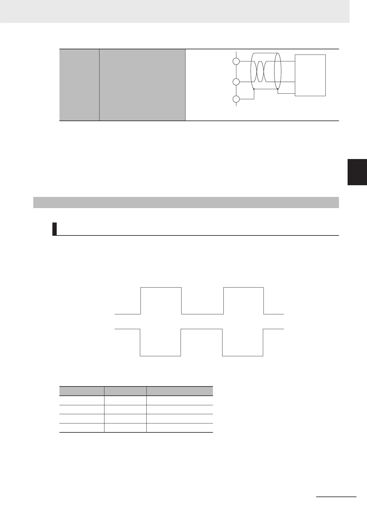
In the differential input for the digital quadrature encoder, when a correct signal arrives in encoder A
+/A-, encoder B+/B-, if the signal level is H in one side, the signal level of the other side is always L.
L
H
L
H
L
H
H
L
H
L
En
coder A+/B+
Encoder A-/B-
You can detect the encoder loss by setting a circuit so that both signals turn H or L when the encoder
is not connected.
Encoder A+/B+ Encoder A-/B- Encoder loss detection
H L Normal
L H Normal
H H Detects loss
L L Detects loss
If loss is detected, the value of Gate3[i].Chan[j].LossStatus becomes 1.
Motor[x].EncLossCount
adds 1 to the count when encoder loss is detected, and subtracts 1 when en-
coder loss is not detected.
However, the minimum value of Motor[x].EncLossCount is 0, and it will never become a negative val-
ue.
3 Configuration Units
3-21
CK3M-series Programmable Multi-Axis Controller User's Manual Hardware (O036)
3-3 Axis Interface Unit
3
3-3-6 Encoder Loss Detection

 Loading...


