Letter Name Function
D EtherCAT communications port opera-
tion indicators
Shows the operation status of EtherCAT.
E Unit connector Connector that connects to the Unit.
F Ethernet communications port opera-
tion indicators
Shows the operation status of Ethernet.
G Ethernet communications connector Connects to an Ethernet network communications cable.
H Watchdog output terminal block Normally in ON state, and switches to OFF when watchdog is
activated.
I USB 2.0 connector USB 2.0 interface connector.
Connects the USB memory
.
J USB connector for maintenance Do not use.
K USB connector for maintenance Do not use.
L DIN Track mounting hook Used to mount the Unit to a DIN Track.
3-1-3
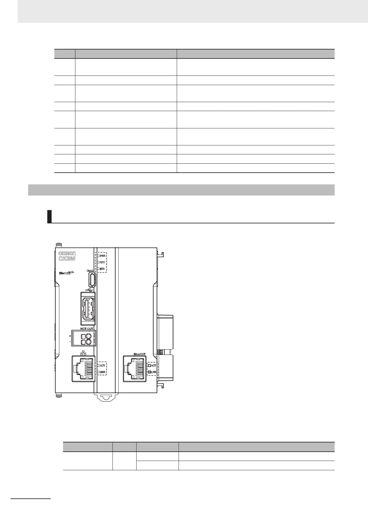
Operation Status Indicators
CPU Unit Operation Status Indicators
The CPU Unit is equipped with indicators to show the current operations status.
CPU Unit Status Indicators
The operating statuses corresponding to the colors and statuses of the indicators are shown below.
Indicator name Color Status Description
PWR Green Lit. Power is supplied to the Unit.
Not lit. Power is not supplied to the Unit.
3 Configuration Units
3-6
CK3M-series Programmable Multi-Axis Controller User's Manual Hardware (O036)

 Loading...


