126
Allocations to Slave Units Section 5-2
Area Allocations According to Communications Mode Number
Word output data, word input data, bit output data, and bit input data are allo-
cated according to communications mode numbers as shown below.
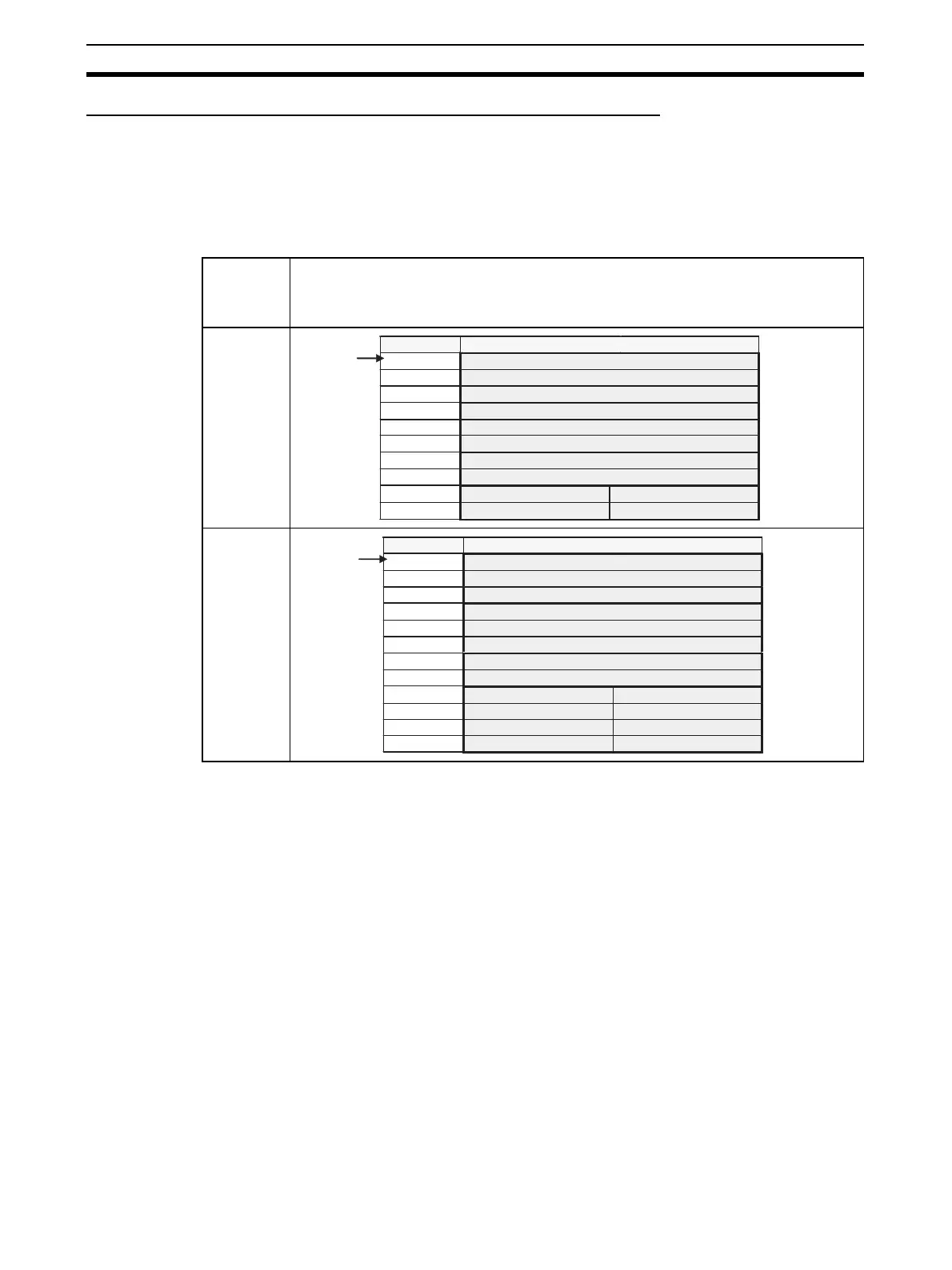
Communications Modes
Other Than Mode 8
The fixed number of node address areas for word output data, word input
data, bit output data, and bit input data are allocated in order in the Special I/O
Unit Area. The first address that is allocated depends on the unit number of
the Master Unit.
Communi-
cations
mode num-
ber
Pattern
0
1
+0 [ OUT0 ]
: :
+7 [ OUT7 ]
+8 [ I N0 ]
: :
+15 [ I N7 ]
+16
+17
+18
+19
Word address Bit 15 Bit 0
Special I/O
Unit Area
CIO 2000 +
(10 x unit
number)
Status
Parameters
Communications Error Flags: OUT0 to OUT7 Participation Flags: OUT0 to OUT7
Communications Error Flags: IN0 to IN7 Participation Flags: IN0 to IN7
+0 [ OUT0 ]
: :
+15 [ OUT15 ]
+16 [ I N0 ]
: :
+31 [ I N15 ]
+32
+33
+34
+35
+36
+37
Word address Bit 15 Bit 0
Special I/O
Unit Area
CIO 2000 +
(10 x unit
number)
Status
Parameters
Communications Error Flags: OUT0 to OUT7 Participation Flags: OUT0 to OUT7
Communications Error Flags: IN0 to IN7
Participation Flags: IN0 to IN7
Communications Error Flags: OUT8 to OUT15
Participation Flags: OUT8 to OUT15
Communications Error Flags: IN8 to IN15
Participation Flags: IN8 to IN15