132
Allocations to Slave Units Section 5-2
Parameters
Note The value of +n depends on the communications mode as follows: The value
is +17 for communications mode number 0, +33 for mode 1, +65 for mode 2,
+49 for mode 3, and +1 for mode 8.
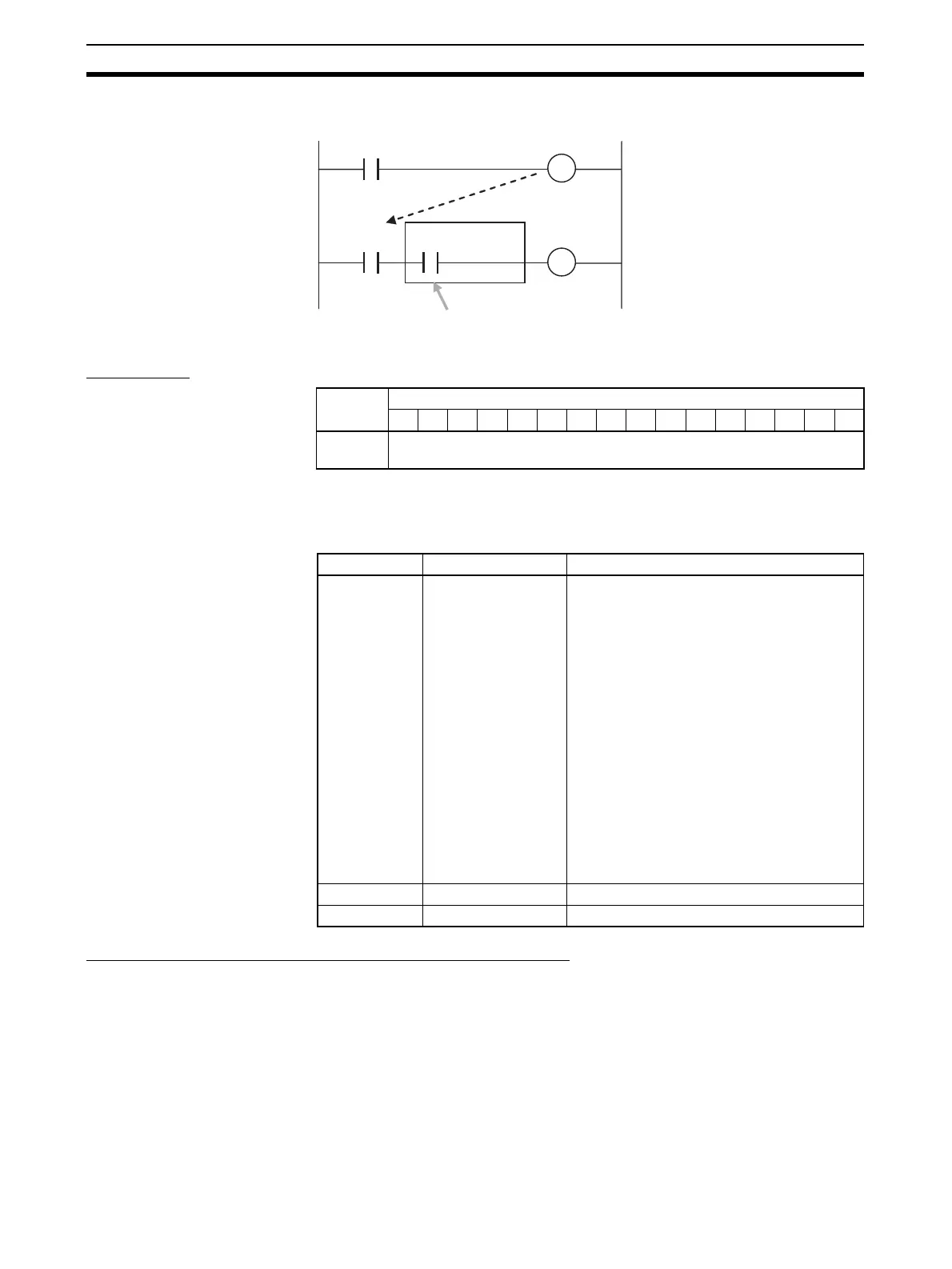
Participation Flags and Communications Error Flags
These flags indicate nodes participating in the network and nodes where
errors have occurred after participation has started.
a
a
Ladder Operation Allowed
Flag in
Registration Table
Enabled Mode (Bit 8)
Normal operation
Normal
operation
Allocated I/O
address
Processing input from
registered Slave Unit
Word Bits
15 14 13 12 11 10 09 08 07 06 05 04 03 02 01 00
+n (See
note.)
Parameters
Bit address Name Contents
00 Remote I/O Commu-
nications Start
Switch
OFF: No processing
ON: Starts remote I/O communications when
turned from OFF to ON. This switch is auto-
matically turned OFF by the system after the
system detects that the switch has turned
ON.
Note 1. This bit is enabled only in I/O Com-
munications Manual Start Mode.
The mode can be selective with the
CX-Integrator.
Note 2. When the I/O Communications
Manual Start Mode is disabled or
when the remote I/O communica-
tions have already been in opera-
tion, a command to start the remote
I/O communications is invalid even if
the system detects the switch is
turned on.
01 Cannot be used. ---
02 to 15 Not used. 0