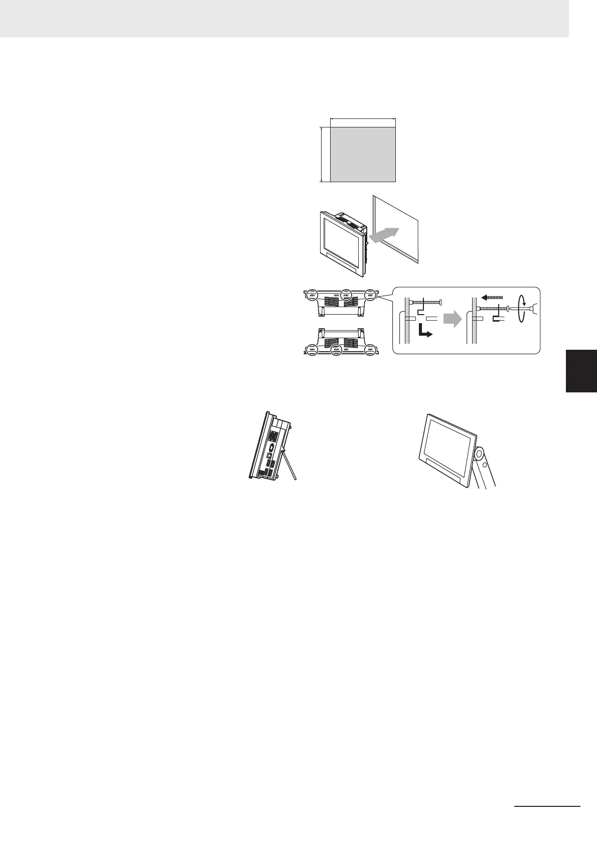
(1) Make a mount hole on the panel.
Panel thickness range: 1.6 to 4.8 mm
Panel material: Metal (iron, aluminum
or stainless)
(Unit: mm)
* No burr allowed
(2) Insert the LCD integrated controller
into the hole, from the front panel.
(3) Use the bracket (supplied with the
product) to secure the controller
and the panel.
Tightening torque: 0.5 to 0.6 N•m
• Mounting the controller to the optional
VESA attachment unit.
VESA-compatible mounting of
the controller is possible by
attaching the optional VESA
attachment unit (FZ-VESA) to
the rear of the controller.
The controller can be placed on
a desk by attaching the optional
desktop stand (FZ-DS) to the
rear of the controller.
• Mounting the controller to the optional
desktop stand.
Top face
297
+1
0
247
+1
0
Bottom face
* For details, refer to the Instruction
Sheet of the desktop stand.
* For details, refer to the Instruction
Sheet of the VESA attachment

 Loading...


