6 - 31
6 I/O Interface
Vision System FH/FZ5 series Hardware Setup Manual (Z366)
6-1 Parallel Interface
6
6-1-6 FZ5-L Series
*1. In camera 2ch type, only STGOUT0 and STGOUT1 can be used.
Note 1. The wire color and the mark correspond to FZ-VP.
Ask your OMRON sales representative for details.
2. No. corresponds to the terminal number of FZ-VPX.
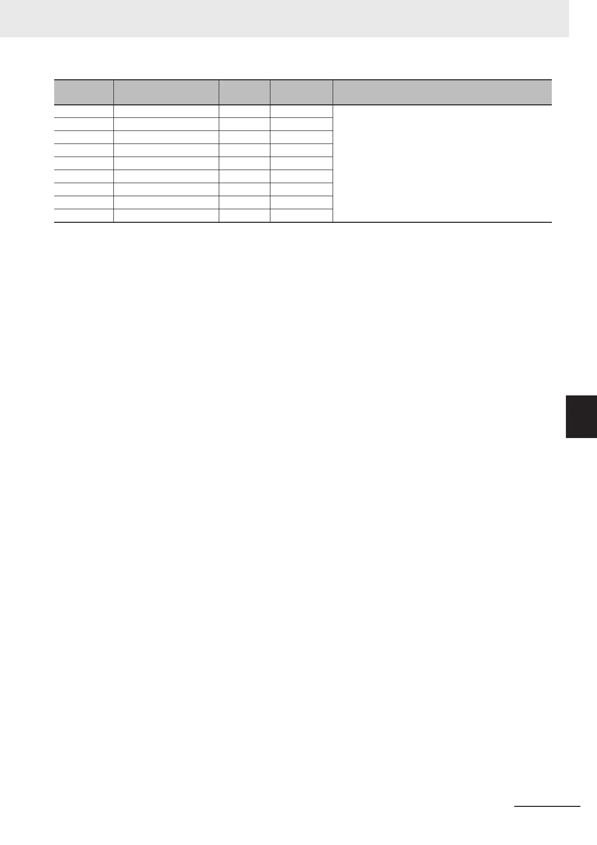
B17 DO0 Gray ŶŶŶŶ Data output
B18 DO2 White ŶŶŶŶ
B19 DO4 Yellow ŶŶŶŶ
B20 DO6 Pink ŶŶŶŶ
B21 DO8 Orange
ŶŶŶŶŶŶŶŶŶŶŶŶŶŶŶŶŶŶŶŶŶŶŶŶŶŶŶŶŶŶŶŶŶŶŶŶŶŶŶŶ
B22 DO10 Gray
ŶŶŶŶŶŶŶŶŶŶŶŶŶŶŶŶŶŶŶŶŶŶŶŶŶŶŶŶŶŶŶŶŶŶŶŶŶŶŶŶ
B23 DO12 White
ŶŶŶŶŶŶŶŶŶŶŶŶŶŶŶŶŶŶŶŶŶŶŶŶŶŶŶŶŶŶŶŶŶŶŶŶŶŶŶŶ
B24 DO14 Yellow
ŶŶŶŶŶŶŶŶŶŶŶŶŶŶŶŶŶŶŶŶŶŶŶŶŶŶŶŶŶŶŶŶŶŶŶŶŶŶŶŶ
B25 DO15 Pink
ŶŶŶŶŶŶŶŶŶŶŶŶŶŶŶŶŶŶŶŶŶŶŶŶŶŶŶŶŶŶŶŶŶŶŶŶŶŶŶŶ
No. Signal name
Wire
color
Mark (red) Function

 Loading...


