3 - 5
3 Configuration
Vision System FH/FZ5 series Hardware Setup Manual (Z366)
3-1 Sensor Controller
3
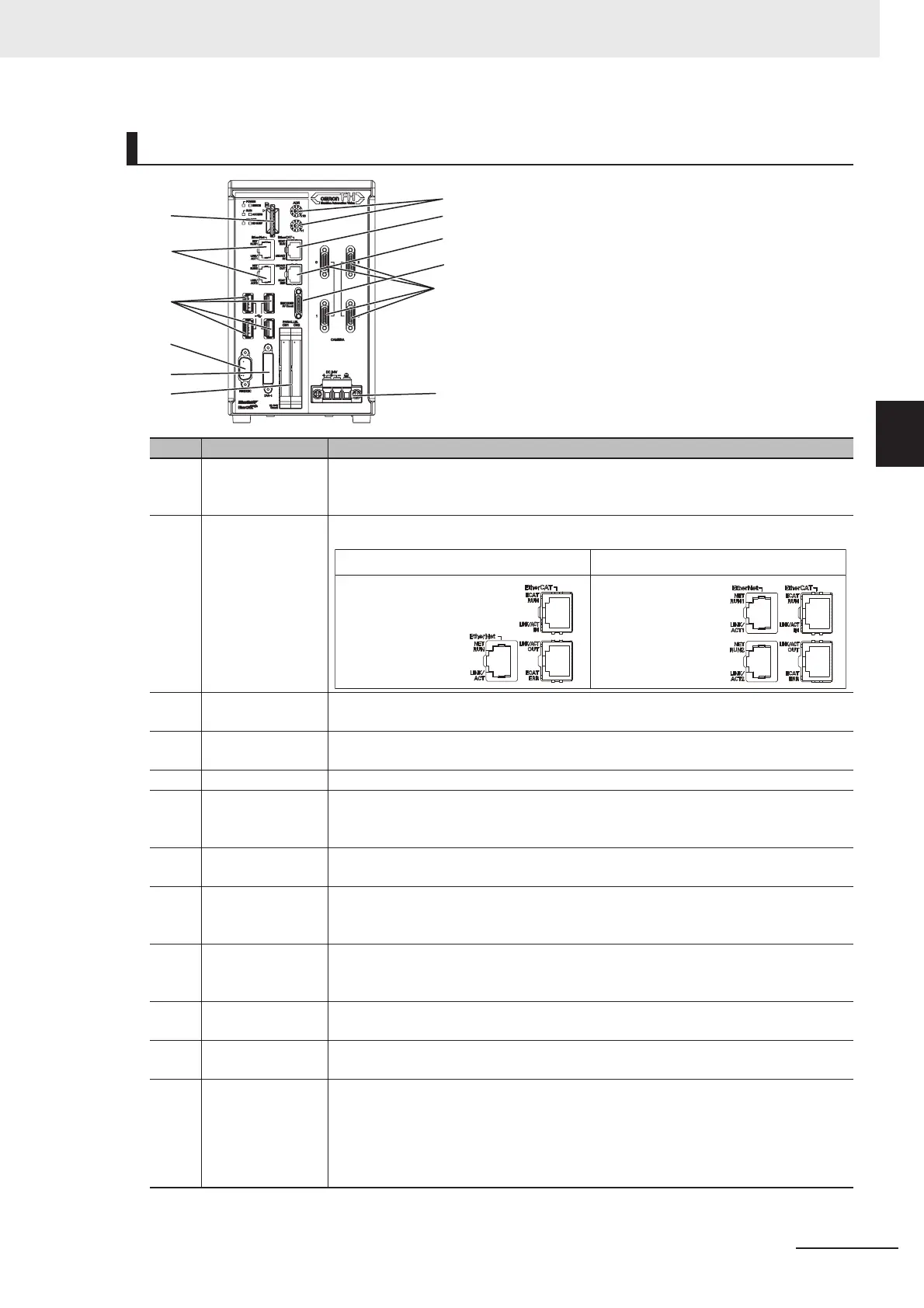
3-1-1 FH-1000/FH-3000 Series
Component Names and Functions
Connector name Description
(A) SD memory card
installation con-
nector
Install the SD memory card. Do not plug or unplug the SD memory card during
measurement operation. Otherwise measurement time may be affected or data
may be destroyed.
(B) Ethernet connec-
tor
Connect an Ethernet device.
(C) USB connector Connect a USB device. Do not plug or unplug it during measurement.
Measurement time might be affected otherwise.
(D) RS-232C connec-
tor
Connect an external device such as a PLC.
(E) DVI-I connector Connect a monitor.
(F) I/O(Parallel) con-
nector (control
lines, data lines)
Connect the controller to external devices such as a sync sensor and PLC.
(G) EtherCAT address
setup volume
Used to set a station address (00 to 99) as an EtherCAT communication device.
(H) EtherCAT commu-
nication connec-
tor (IN)
Connect the opposed EtherCAT device.
(I) EtherCAT commu-
nication connec-
tor (OUT)
Connect the opposed EtherCAT device.
(J) Encoder connec-
tor
Connect an encoder.
(K) Camera connec-
tor
Connect cameras.
(L) Power supply ter-
minal connector
Connect a DC power supply. Wire the FH Sensor Controller independently on other
devices.
Wire the ground line. Be sure to ground the FH Sensor Controller alone.
Use an attachment power terminal (male) for installation.
For details, refer to 5-3-2 FH-1000/FH-3000 Series on page 5-7.
(A)
(B)
(C)
(D)
(E)
(F)
(G)
(H)
(I)
(K)
(L)
(J)
Camera 2ch type
Ethernet port and
EtherNet/IP port are
sharing use.
Upper port :
Ethernet port
Lower port :
Ethernet port and
EtherNet/IP port are
sharing use.
Camera 4ch/8ch type

 Loading...


