Order of Powering On and Off the Controller and Controlled Sys-
tem
Outputs from Units, such as DC Output Units, may malfunction momentarily when the Unit power sup-
ply is turned ON. This may cause problems in the system if the Unit power supply is turned ON after
the I/O power supply (i.e. controlled system's power supply) is turned ON. To prevent possible mal-
functions, configure an external circuit that prevents the power supply to the controlled system from
turning ON before the power supply to the Controller itself.
Also, the external circuit must be configured so that the Unit power supply turns OFF only after the
power supply to the controlled system has turned OFF
.
Precautions for Safe Use
It takes a certain time for startup to enter RUN mode after the power supply is turned ON, de-
pending on the type and configuration of the Unit and its settings.
During startup, the outputs for NX Units on the CPU Rack will be OFF. Note that the outputs on
the slaves will behave according to the setting values.
Therefore, use the system-defined variables and the device variables for each Unit in the user
program to confirm that startup processing and I/O data communications are established before
attempting control operations.
External communications are also not performed during startup.
Failure of the Output Section of the Output Unit
It is possible for an output to remain ON due to a malfunction in the internal circuit of the Output Unit,
such as a relay or transistor in the output section. Be sure to add any circuits necessary outside of the
Controller to ensure the safety of the system in the event that an output section fails to go OFF.
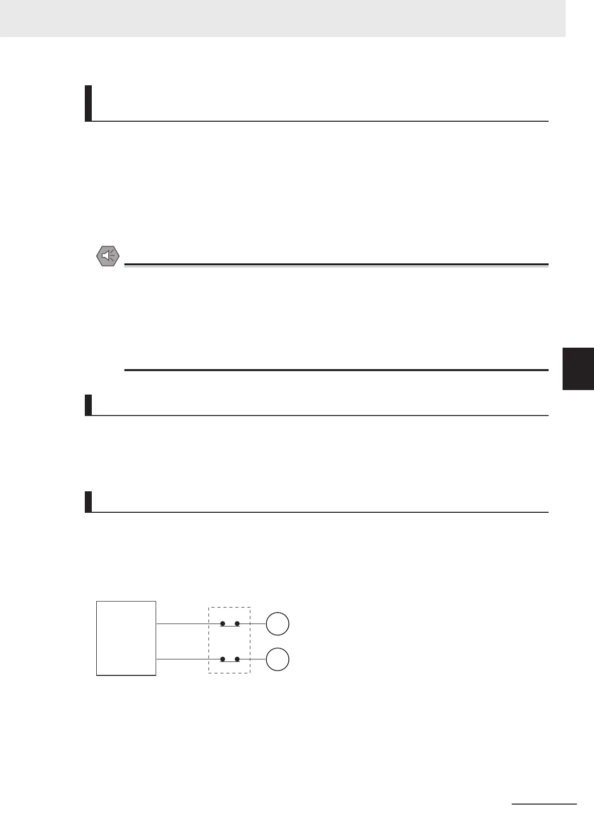
Interlock Circuits
When the Controller controls an operation such as the clockwise and counterclockwise operation of a
motor, provide an external interlock such as the one shown in the following example to prevent both
the forward and reverse outputs from turning ON at the same time if required by the application.
Example:
Controller
Interlock circuit
Motor counterclockwise
Motor clockwise
MC
2
ON_MC1
MC1
ON_MC2
MC1
MC2
This circuit prevents outputs MC1 and MC2 from both being ON at the same time even if both Control-
ler outputs ON_MC1 and ON_MC2 are ON due to a malfunction.
5 Installation and Wiring
5-7
NX-series NX502 CPU Unit Hardware User's Manual (W629)
5-2 Fail-safe Circuits
5

 Loading...


