3-5
X Bus Units
The X Bus Units are used to connect with large capacity data communications.
Up to four X Bus Units can be connected to the CPU Unit.
The X Bus Unit power is supplied directly from the Unit power supplied to the CPU Unit. A total of 50
W of DC power can be supplied. Therefore, external power supply is not required.
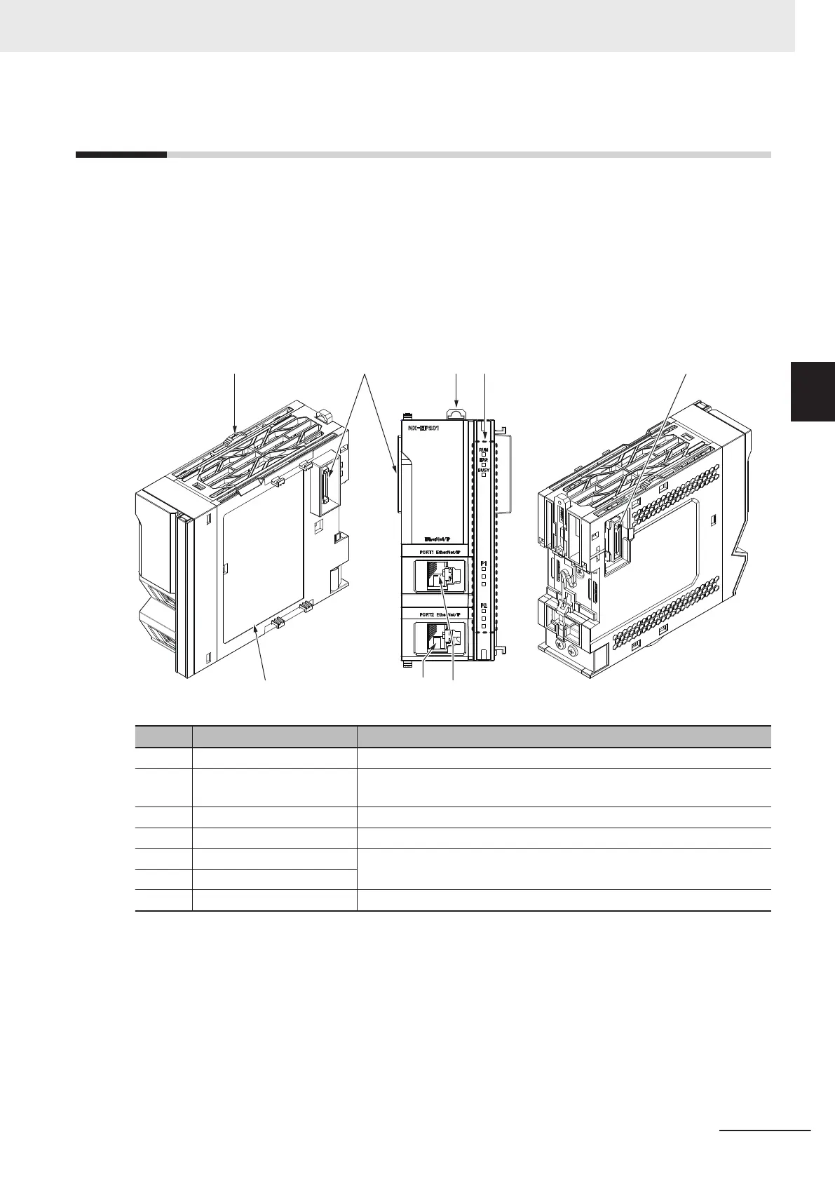
The following is an example of X Bus Unit’s part names and functions with the EtherNet/IP Unit.
For details on the part names and functions of X Bus Units, refer to the user’s manual for each X Bus
Unit.
(G)
(B) (C)(A) (D) (B)
(E)(F
)
Symbol Name Function
A Slider The slider is used to slide the X Bus Unit when installing or removing.
B X Bus connector This connector is used to connect with the CPU Units or other X Bus
Units.
C DIN Track mounting hook This hook is used to mount the CPU Unit to a DIN Track.
D Operation Status Indicators The indicators show the current operating status of the Unit.
E EtherNet/IP port (port 1) They are communications ports for EtherNet/IP connection.
F EtherNet/IP port (port 2)
G Unit specifications The specifications of the Unit are given here.
3 Configuration Units
3-17
NX-series NX502 CPU Unit Hardware User's Manual (W629)
3-5 X Bus Units
3

 Loading...


