3-1-2
Part Names and Functions
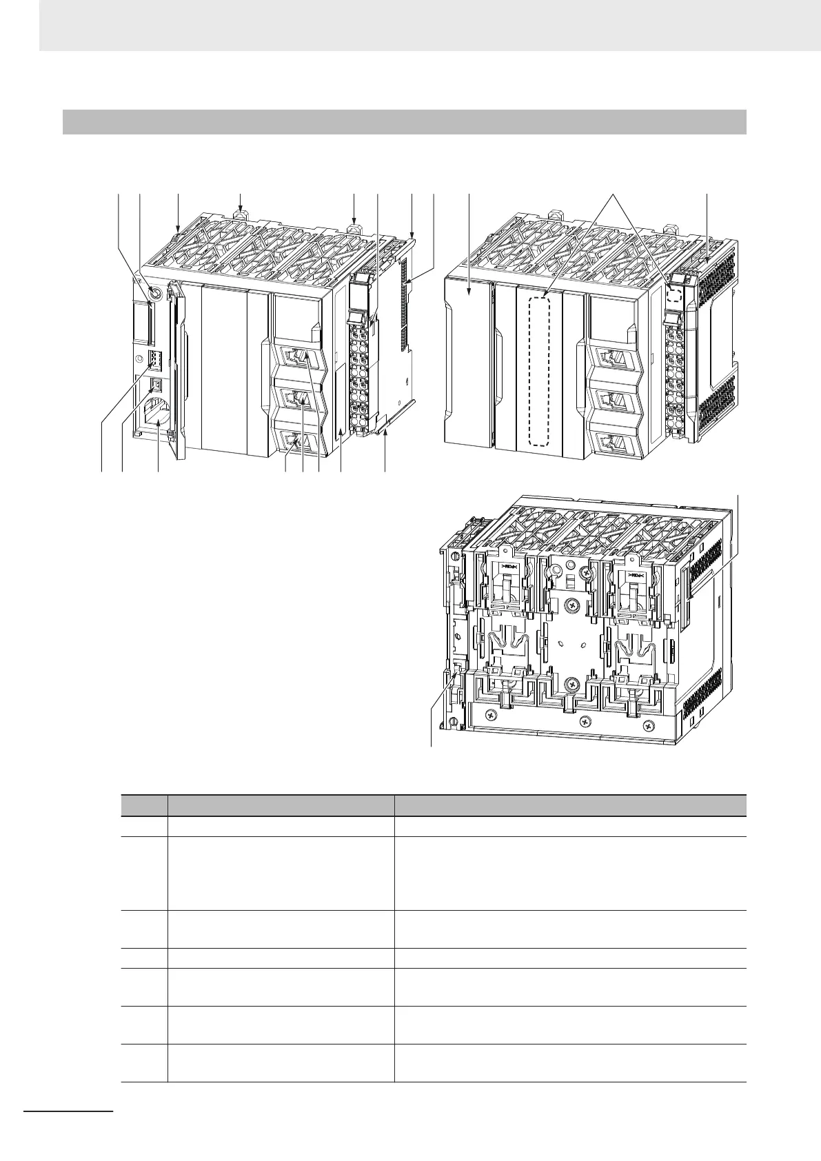
This section explains parts of the CPU Unit and their functions.
(A) (B) (D) (E)
(H)(I)
(C)
(F) (G) (P)
(J)
(Q)
(S)
(L)
(O)
(M)(N)
(D)
(F)
(K)
(R)
Letter Name Function
A SD Memory Card connector Connects the SD Memory Card to the CPU Unit.
B SD Memory Card power supply switch Turns OFF the power supply so that you can remove the SD
Memory Card.
5-3-9 Installing and Removing the SD Memory Card on page
5-24
C Slider The slider is used to slide the X Bus Unit when installing or
removing.
D DIN Track mounting hooks These hooks are used to mount the CPU Unit to a DIN Track.
E Terminal block The terminal block is used for wiring for the Unit power supply
and grounding cable.
F Unit hookup guides These guides are used to mount an NX Unit or the End Cov-
er
.
G
NX bus connector This connector is used to connect the CPU Unit to the NX
Unit on the right of the CPU Unit.
3 Configuration Units
3-4
NX-series NX502 CPU Unit Hardware User's Manual (W629)

 Loading...


