2-3
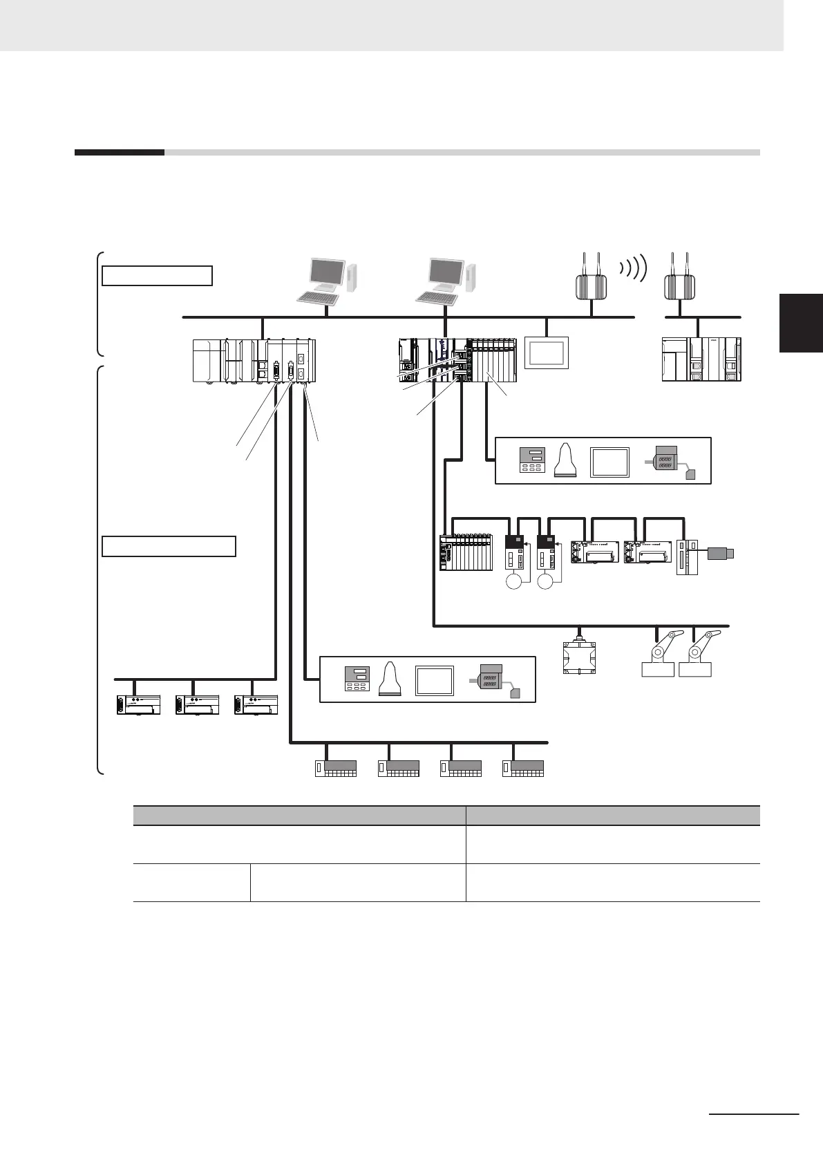
Network Configuration
You can make networks in the following layers with an NJ/NX-series Controller.
For details on communications networks that you can connect to, refer to the NJ/NX-series CPU Unit
Software User’s Manual (Cat. No. W501).
POWER
PORT2
EtherCAT
Slave Terminal
Vision
Systems
Sysmac
Studio
EtherNet/IP
DeviceNet
EtherCAT
CompoNet
REMOTE
TERMINAL
0 1 2 3 4 5 6 7 8 9
10 11
12
13
14
15
OUT
CRT1
-
OD16
MS
NS
WORD
NODE ADR
REMOTE
TERMINAL
0 1 2 3 4 5 6 7 8 9
10 11
12
13
14
15
OUT
CRT1
-
OD16
MS
NS
WORD
NODE ADR
REMOTE
TERMINAL
0 1 2 3 4 5 6 7 8 9
10 11
12
13
14
15
OUT
CRT1
-
OD16
MS
NS
WORD
NODE ADR
EtherNet/IP
Information Level
Built-in
EtherNet/IP port 1
Built-in EtherNet/IP
port 2
Built-in EtherCAT
port
Built-in EtherNet/IP ports
CompoNet Master Unit
CompoNet slaves
DeviceNet slaves
DeviceNet Unit
NJ-series
CPU Unit
Field Level
NX-series
NX502
CPU Unit
Serial Communica-
tions Unit
RS-232C,
RS-422A/485
RFID system Robots
Servo Drives
General-purpose
slaves
Serial communications devices
NX-series Communications
Interface Unit
General-purpose components or OMRON components
Serial communications devices
General-purpose components or OMRON components
NJ/NX-series
CPU Unit
Programmable
Terminal
FA Wireless
LAN Unit
FA Communica-
tions Software
Connection Connection method
Sysmac Studio Use the built-in EtherNet/IP port (1 or 2) or an
EtherNet/IP Unit.
*1
Between Controllers NJ/NX-series Controller or CJ-series PLC Use the built-in Ethernet/IP port (1 or 2) or a port on an
EtherNet/IP Unit.
*1
2 System Configuration
2-9
NX-series NX502 CPU Unit Hardware User's Manual (W629)
2-3 Network Configuration
2

 Loading...


