Not all of the combinations of the DIN Tracks and End Plates listed above are possible.
Confirm applicability of the combinations in the following table.
DIN Track model
PFP-M
(OMRON)
CLIPFIX 35
(Phoenix Contact)
PFP-50N Possible Possible
PFP-100N Possible Possible
NS 35/ 7,5 PERF Possible Possible
NS 35/ 15 PERF Not possible Possible
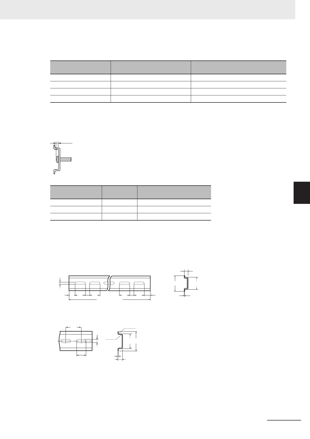
Also, use screws and washers of the following sizes to fix the DIN Tracks.
(a): Dimensions from the screw head to the fastening surface
DIN Track model
Applicable
screw size
(a)
PFP-50N M4 4.1 mm max.
NS 35/ 7,5 PERF M6 4.6 mm max.
NS 35/ 15 PERF M6 10 mm max.
If you use any DIN Track other than those listed in the table above, refer to the dimensions shown in
5-3-14 Assembled Appearance and Dimensions on page 5-32 and use proper screws and washers.
l
DIN T
racks
PFP-100N/50N DIN Track
1,000 (500)
*
1
15
1
0
4.5
25 25 25
10
25 15 (5)
*1
1
7.3±0
.15
35±0.3
27±0.15
*1. PFP-50N dimensions are
given in parentheses.
NS 35/ 7,5 PERF
NS 35/ 15 PERF
5 Installation and Wiring
5-13
NX-series NX502 CPU Unit Hardware User's Manual (W629)
5-3 Mounting and Removing Units
5
5-3-2 Preparations for Installation

 Loading...


