Symbol Terminal name Description Reference
+/- Unit power supply termi-
nals
These terminals are connected to the
Unit power supply
.
The + terminals and - terminals are in-
ternally connected to each other
.
5-4-1 Wiring the Unit Power
Supply on page 5-44
COM Common terminal Common terminal for the input circuits Input Specifications on page
3-14
00 to 13 Input terminals General-purpose input A
NC NC Do not connect anything. ---
l
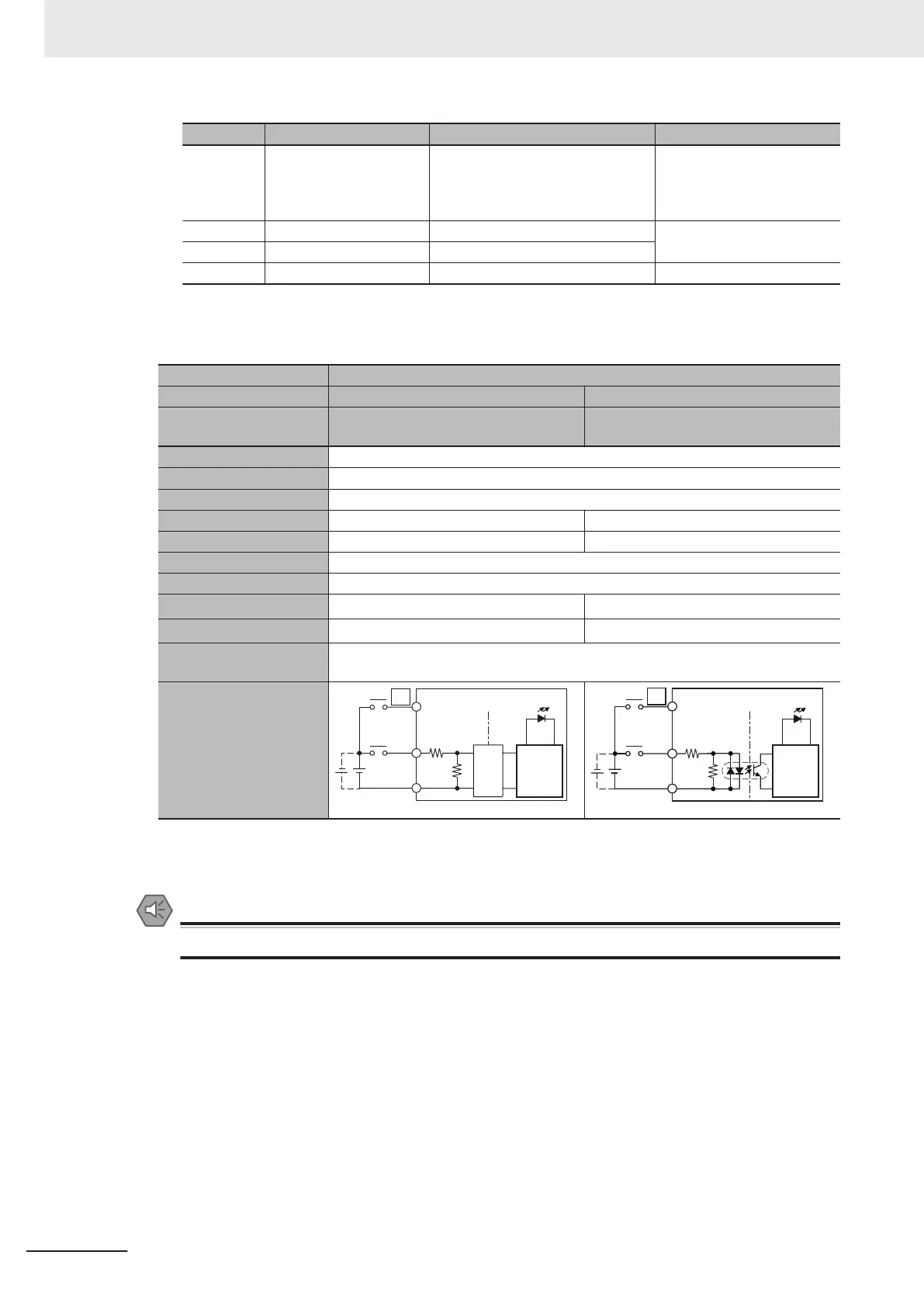
Input Specifications
The specifications depend on the input terminal numbers of the model.
Item Specification
Input type General-purpose input A General-purpose input B
Input terminal number
NX1P2-££40DT£: 00 to 15
NX1P2-9£24DT£: 00 to 13
NX1P2-££40DT£: 16 to 23
NX1P2-9£24DT£: None
Internal I/O common For both NPN/PNP
Input voltage 24 VDC (15 to 28.8 VDC)
Connected sensor Two-wire or three-wire sensors
Input impedance 4.0 kΩ 4.3 kΩ
Input current 5.8 mA typical 5.3 mA typical
ON voltage 15 VDC min.
OFF voltage/current 5 VDC max./1 mA max.
ON response time
*1
2.5 µs max. 1 ms max.
OFF response time
*1
2.5 µs max. 1 ms max.
ON/OFF filter time
*2
No filter, 0.25 ms, 0.5 ms, 1 ms (default), 2 ms, 4 ms, 8 ms, 16 ms, 32 ms, 64 ms, 128 ms,
256 ms
Circuit configuration
Input indicator
Isola-
tion
circuits
Internal
circuits
COM
00
4.0 kΩ
1.1 kΩ
15 (13)
910 Ω
4.3 kΩ
Input indicator
Internal
circuits
COM
. . .
. . .
*1. These values are the fixed response time needed by the hardware. A value from 0 to 32 ms (default: 1 ms) that is set
on the Support Software is added to these values.
*2. Set the filter time for every 4 points.
Precautions for Safe Use
Do not apply voltages that exceed the rated value.
3 Configuration Units
3-14
NX-series NX1P2 CPU Unit Hardware User’s Manual (W578)
 Loading...


