Output Terminal Block
l
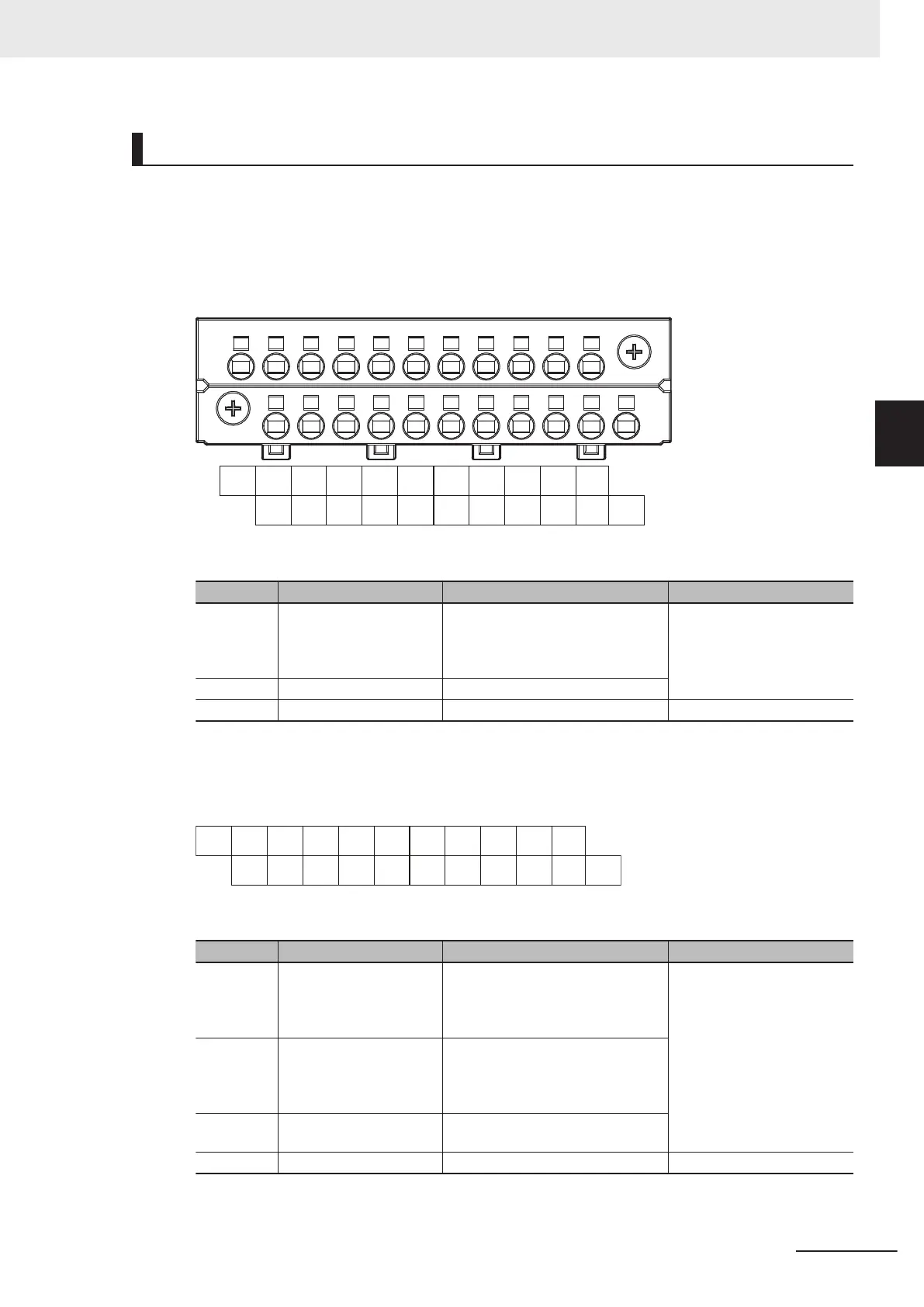
Terminal Arrangement
The description is given for each CPU Unit model.
a.
NX1P2-££40DT
NC
14
1
5
12
13
10
11
08
09
NC
C1
(0V)
06
07
04
05
02
03
00
01
NC
NC
C0
(0V)
Symbol Terminal name Description Reference
C0 (0V), C1
(0V)
Common terminal Connected to the 0-V side of the I/O
power supply
.
C0 (0V) and C1 (0V) are independent
from each other inside the CPU Unit.
Output Specifications on page
3-17
00 to 15
Output terminals NPN (sinking) type output
NC NC Do not connect anything. ---
b.
NX1P2-££ 40DT1
The appearance of the terminal block is the same as (a).
NC
14
1
5
12
13
10
11
08
09
C1
(+V)
0V1
06
07
04
05
02
03
00
01
C0
(+V)
NC
0V0
Symbol Terminal name Description Reference
C0 (+V),
C1 (+V)
Common terminal Connected to the 24-V side of the I/O
power supply
.
C0 (+V) and C1 (+V) are independent
from each other inside the CPU Unit.
Output Specifications on page
3-17
0V0, 0V1
0 V terminal Supplies 0 V for the internal circuits for
driving.
0V0 and 0V1 are independent from
each other inside the CPU Unit.
00 to 15 Output terminals PNP (sourcing) type output with the
load short-circuit protection function
NC NC Do not connect anything. ---
c.
NX1P2-9£24DT
3 Configuration Units
3-15
NX-series NX1P2 CPU Unit Hardware User’s Manual (W578)
3-1 CPU Units
3
3-1-4 Terminal Blocks
 Loading...


