Appendix BSpecifications
133
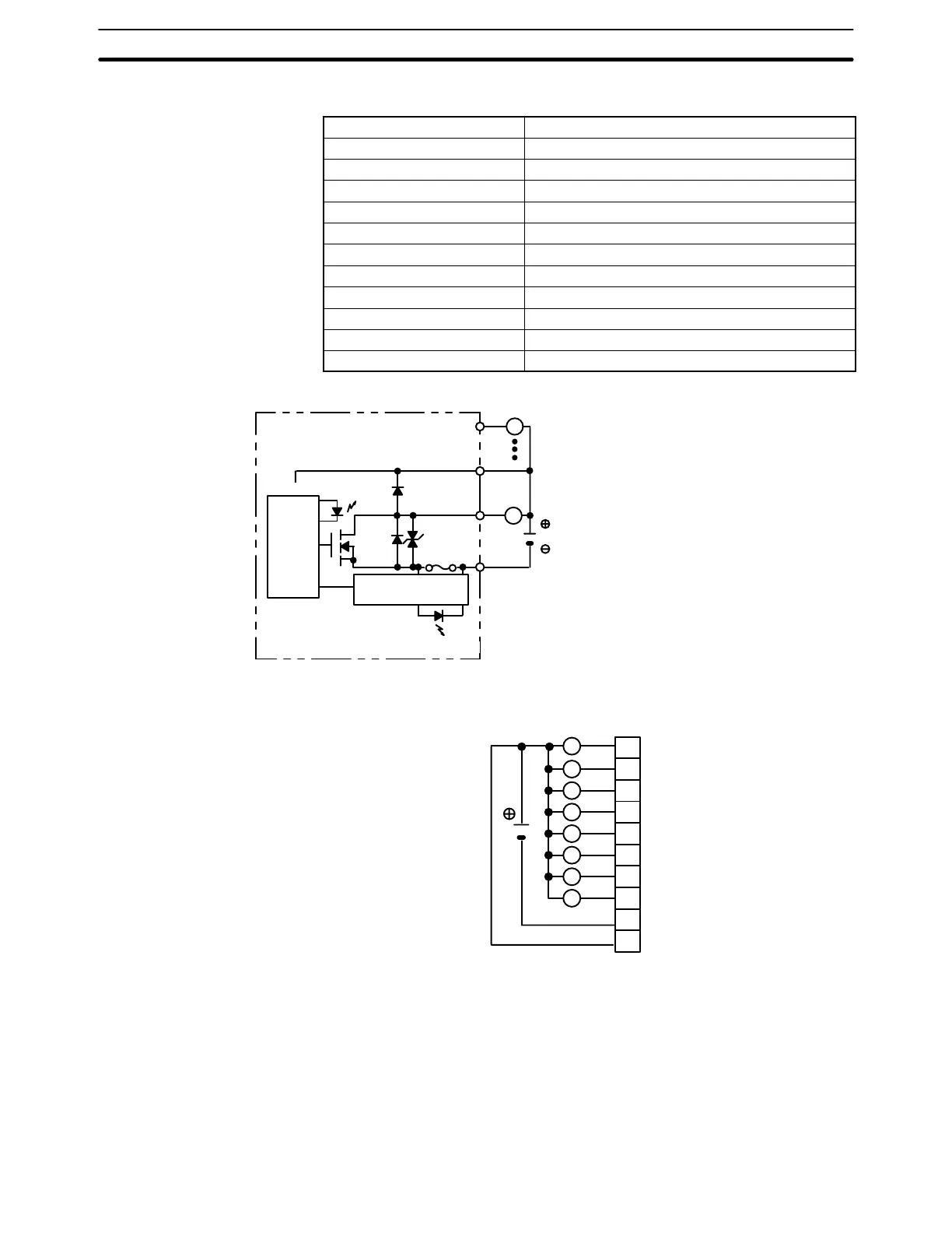
Transistor Output Unit C200H-OD213
Max. Switching Capacity 2.1 A 24 VDC
+10%
/
–15%
(5.2 A/Unit) NPN output
Min. Switching Capacity None
Leakage Current 0.1 mA max.
Residual Voltage 1.4 V max.
ON Response Time 0.2 ms max.
OFF Response Time 0.3 ms max.
No. of Circuits 1 (8 points/common)
Internal Current Consumption 140 mA 5 VDC max.
Fuse Rating 8 A 125 V (5.2-dia.x20)
Power for External Supply 30 mA 24 VDC
+10%
/
–15%
min.
Weight 250 g max.
Dimensions A-shape
Circuit Configuration
Internal
Circuit
L
OUT
COM
OUT
Output indicator
L
+ V
24 VDC
Fuse blowout
detection circuit
Fuse
F indicator
Fuse: UL-TSC-8A-N1 (Nagasawa)
8 A 125 V 5.2-dia 20
Note When the fuse blows, the F indicator lights and bit 08 turns ON. Bits 08 through 15 cannot be used as IR bits.
Terminal Connections
24 VDC
(2.1 A max., 5.2 A/Unit)
L
L
L
L
L
L
L
L
A0
A1
A2
A3
A4
A5
A6
A7
A8
A9
0
1
2
3
4
5
6
7
COM (OV)
24 VDC
Note Be sure to supply power to A9; otherwise current will leak through the load while the output is OFF.