19
C200HS-CPU21-E/CPU21-EC/CPU23-E/CPU31-E/CPU33-E
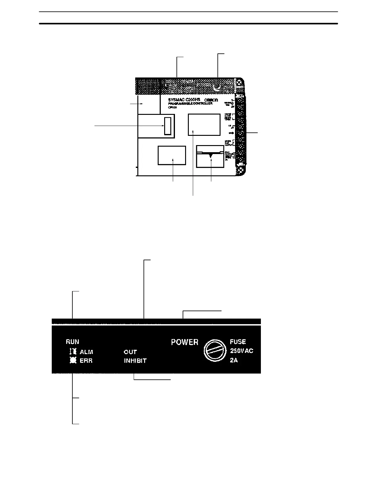
Memory Casette compartment
Bus connector:
Available only with the CPU31-E
and CPU33-E. Use this connector
when SYSMAC NET Link Unit or
SYSMAC LINK Unit is used.
RS-232C
connector
Cable connector for
peripheral devices
Battery/Switch compartment
Power fuse (MF51NR, 5.2 dia. x 20 mm):
C200HS-CPU21-E/CPU21-EC/CPU31-E:
2 A, 250 V
C200HS-CPU23-E/CPU33-E: 5 A, 125 V
Indicators
Removable terminal block
2-2-2 CPU Indicators
The following table shows the indicators that are located on the front panel of the
CPUs.
RUN (green):
Lights when the PC is
operating normally.
POWER (green):
Lights when power is
supplied to the CPU.
OUT INHIBIT (red):
Lights when the Load OFF
flag (SR bit 25215) turns ON,
at which time all the outputs
are turned OFF.
ALM (blinking red):
Blinks if an error occurs that
does not stop the CPU.
ERR (solid red):
Lights if an error occurs that stops the
CPU, at which time the RUN indicator
turns OFF and the outputs are turned
OFF.
COMM 2
COMM1 (orange) (Note “COMM” on CPU01-E/CPU01-EC/CPU03-E):
Lights when a peripheral device is in operation.
COMM2 (orange):
Available only with the CPU21-E, CPU21-EC, CPU23-E, CPU31-E,
and CPU33-E. Lights when the CPU is communicating via the
RS-232C connector.
COMM 1
CPUs Section 2-2