57
4-10 External Wiring
If power cables must be run alongside the I/O wiring (that is, in parallel with it), at
least 300 mm must be left between the power cables and the I/O wiring as shown
below.
Low current cable
Control cable
Power cable
300 mm min.
300 mm min.
1
2
3
Class-3 ground
Where: 1 = I/O wiring
2 = General control wiring
3 = Power cables
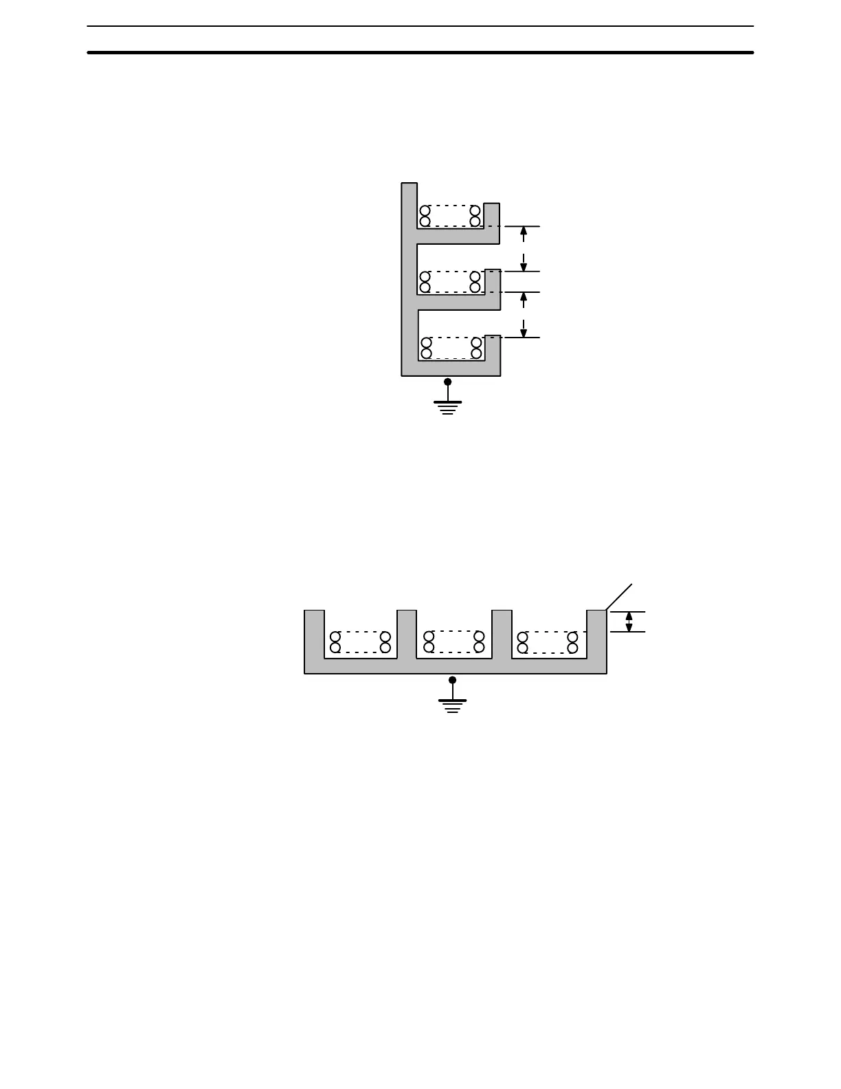
If the I/O wiring and power cables must be placed in the same duct (for example,
where they are connected to the equipment), they must be shielded from each
other using grounded metal plates.
Metal plate (iron)
123
200 mm min.
Class-3 ground
Where: 1 = I/O wiring
2 = General control wiring
3 = Power cables
4-11 System Design and Safety Considerations
When designing a C200HS system, be sure to consider the following points:
• Power supply system wiring and emergency stop circuit
• Interlock circuit
• Programmable Controller power interruptions
4-11-1 Power Supply System and Emergency Stop Circuit
The power section, control section, PC System, and the DC I/O system should
all be wired separately.
System Design and Safety Considerations Section 4-11