25
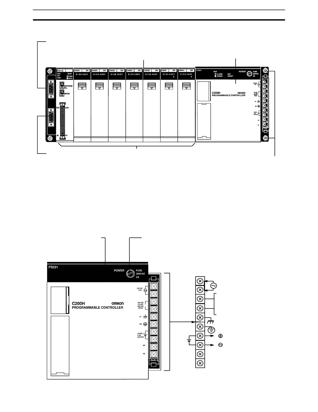
The parts of an Expansion I/O Rack are shown in the following diagram.
I/O Connecting Cable Connector:
Connects Expansion I/O Rack to
next Expansion I/O Rack.
When not used, cover with a cap.
Backplane mounting screws
(four, with 4-mm dia. heads)
Power Supply
Backplane
I/O Units
I/O Connecting Cable Connector:
Connects Expansion I/O Rack to pre-
ceding Expansion I/O Rack or to CPU.
2-4 Power Supply Unit
The Power Supply used for Expansion I/O Racks is available in three models.
Two run on 100 to 120 or 200 to 240 VAC, and the other runs on 24 VDC. Also,
one of the AC Power Supply Units conforms to EC directives. Be very careful not
to provide an AC power supply to a DC-type Unit.
AC Power Supply Unit: C200H-PS221
POWER indicator (green):
Lights when power is
supplied to Power Supply
Power fuse:
2 A, 250 V
(5.2-dia. x 20) MF51NR
Voltage selector terminals
Short: 100 to 120 VAC
Open: 200 to 240 VAC
Terminals
for exter-
nal con-
nections
NC
NC
GR
LG
AC Input
+
24 VDC, 0.3
A output
Power Supply Unit Section 2-4