54
Relationship between OFF Current (I
OFF
) of the PC and Leakage Current of
the Sensor (I
leak
)
I
OFF
y I
leak
For details, refer to sections providing precautions on leakage current. The val-
ue of I
OFF
will vary depending on the on the Unit. However, the value for Input
Units for which OFF current specifications are not listed will be 1.3 mA.
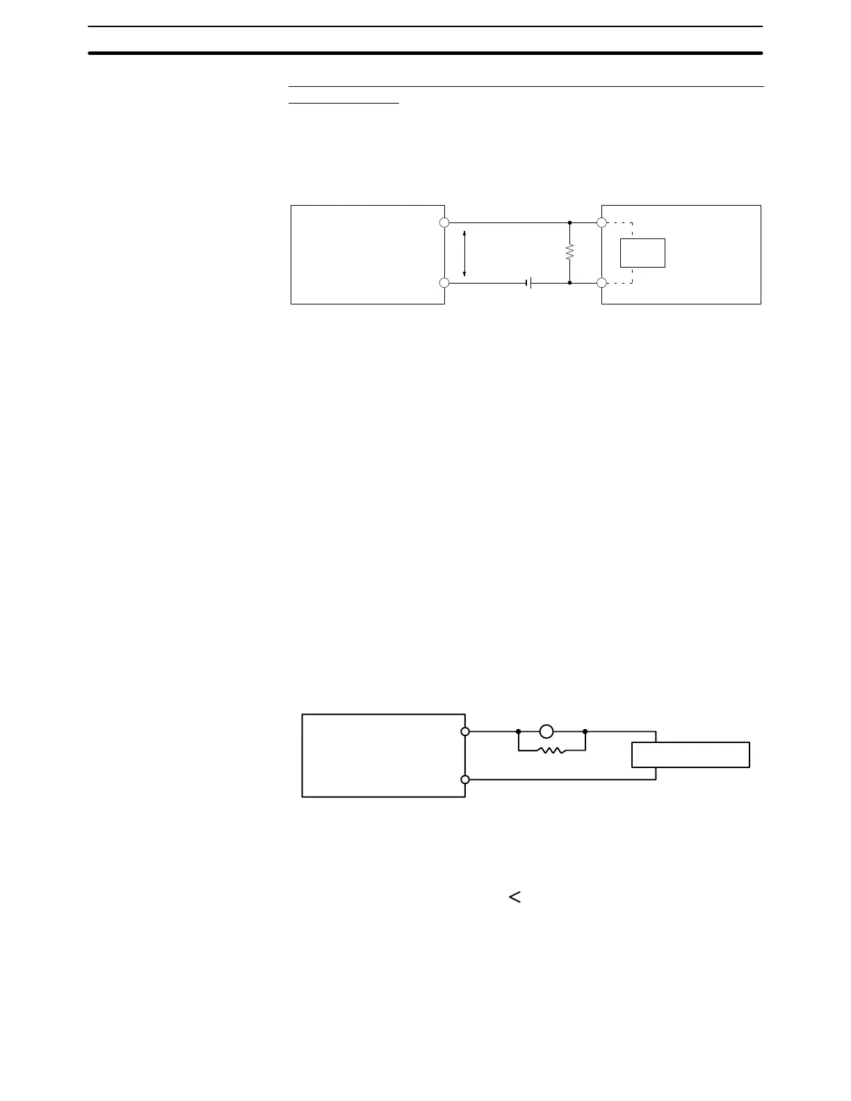
R
IN
RV
R
V
CC
Two-wire sensor
DC Input Unit
V
CC
: Power supply voltage V
R
: output residual voltage in the sensor
V
ON
: PC ON voltage I
OUT
: control output of the sensor (load current)
I
ON
: PC ON current I
leak
: leakage current of the sensor
I
OFF
: PC OFF current R: bleeder resistance
R
IN
: PC input impedance
4-9 Output Circuits
When wiring outputs, take the following points into consideration.
If a load connected to the output terminals is short-circuited, output elements
and printed boards may be damaged. To guard against this, incorporate a
fuse in an external circuit.
When connecting TTL circuits to transistor Output Units, it is necessary to con-
nect a pull-up resistor and a CMOS IC between the two. This is because of the
residual voltage left on the transistor output after the output turns OFF.
Output Leakage Current If there is a possibility of leakage current causing a transistor or triac to malfunc-
tion, connect a bleeder resistor across the output as shown below.
PC
Load power supply
OUT
COM
Bleeder resistor
L
R
Determine the value and rating for the bleeder resistor using the following for-
mula.
E
on
I
–––
R
Where
E
on
= ON voltage of the load in V
I = leakage current in mA
R = bleeder resistance in kΩ
Output Short-circuit
Protection
Transistor Output Residual
Voltage
Output Circuits Section 4-9