49
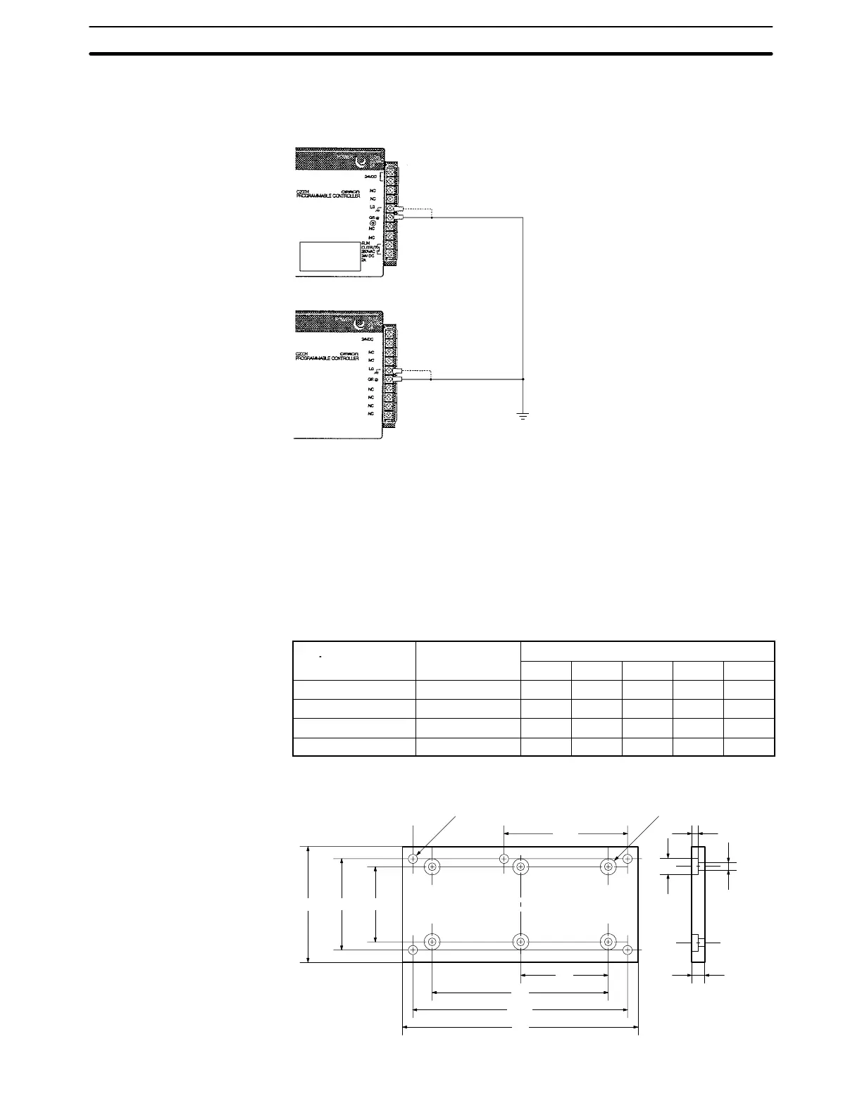
When using an Expansion I/O Rack, the Rack must also be grounded to the GR
terminal. The same ground can be used for all connections.
Screw (3.5 mm
head with self-rais-
ing pressure plate)
C200HS-CPU01-E/CPU01-EC/CPU03-E/CPU21-E/CPU21-EC/CPU31-E/CPU23-E/CPU33-E
Screw (3.5 mm head with
self-raising pressure plate)
C200H-PS221/PS221-C/PS211
I/O Power Supply Unit
Ground wire
(2 mm
2
or
larger)
Note The LG terminal is not provided for the C200HS-CPU01-EC CPU and
C200H-PS221-C I/O Power Supply Unit.
4-6 Backplane Insulation Plate
If there is an electric potential difference between grounds when devices are
wired separately, then use a Backplane Insulation Plate. There are four models
available, corresponding to the number of slots in the Backplane. The dimen-
sions at locations A, B, C, D, and E are shown below in millimeters for each Back-
plane Insulation Plate model.
Specifications Model
Dimensions (mm)
E D C B A
For 3 slots C200H-ATT31 261 210 --- --- 246
For 5 slots C200H-ATT51 331 280 --- --- 316
For 8 slots C200H-ATT81 436 385 --- --- 421
For 10 slots C200H-ATTA1 506 455 227.5 270.5 491
M4 screws for mounting to PC
(4/5 places)
5-dia. holes for mounting
Base Insulation Plate
(4/6 places)
135 (118)
110
(B)
C
D
(A)
E
12 dia.
6
5 dia.
10
Backplane Insulation Plate Section 4-6