!
39
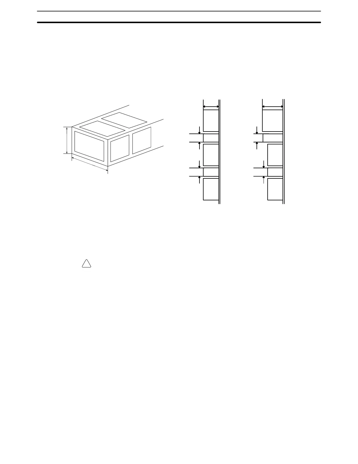
3-3 Installing Racks
The following figures show two side views, each consisting of a mounted CPU
and two Expansion I/O Racks. Provide a space of 20 mm minimum on the upper
and lower sides of each duct for ventilation and Unit replacement purposes.
CPU
Duct
I/O
118 mm
Duct
I/O
30 mm
30 mm
40 mm
30 mm
CPU
Duct
I/O
143 mm
Duct
I/O
30 mm
30 mm
C200HS-
CPU01-E/CPU01-EC/
CPU03-E
C200HS-CPU21-E/CPU21-EC/
CPU23-E/CPU31-E/CPU33-E
Each Rack must be mounted vertically, that is, with the printing on the front pan-
els oriented as it would normally read. Racks may be directly mounted to any
sturdy support meeting the environmental specifications.
Whenever possible, use wiring conduit to hold the I/O wiring. Standard wiring
conduit should be used, and it should be long enough to completely contain the
I/O wiring and keep it separated from other cables.
Caution Racks must be mounted horizontally so that the Units are upright (i.e., not upside
down or lying on their backs).
Installing Racks Section 3-3