53
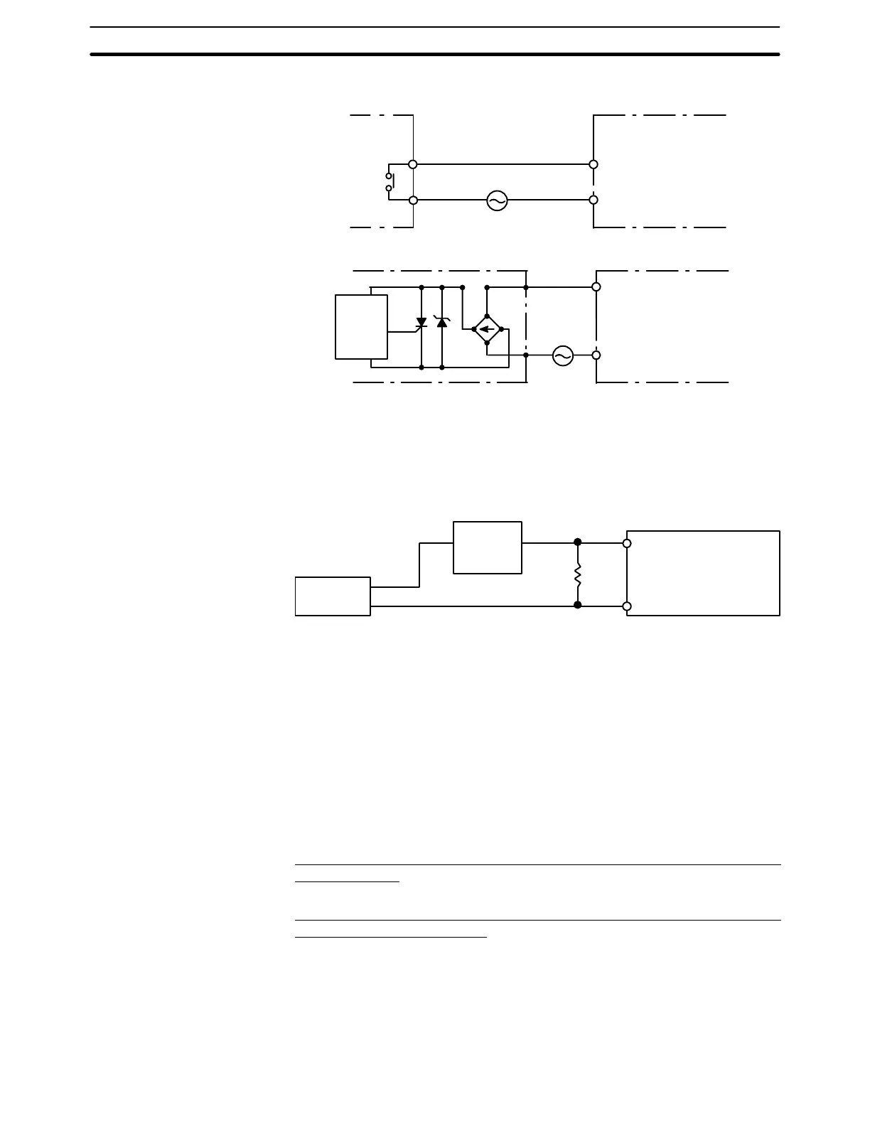
AC Input Units
COM
Contact output
IN AC input
COM
AC Switching
IN AC input
Prox-
imity
switch
main
circuit
4-8 Input Circuits
Input Leakage Current When two-wire sensors, such as photoelectric sensors, proximity sensors, or
limit switches with LEDs, are used for 12/24-VDC input devices, the input bit may
be turned ON erroneously by leakage current. In order to prevent this, connect a
bleeder resistor across the input as shown below.
Sensor
Input
power
supply
Bleeder
resistor
R
PC
If the leakage current is less than 1.3 mA, there should be no problem. If the leak-
age current is greater than 1.3 mA, determine the resistance and power rating
for the bleeder resistor using the following formulas.
For standard I/O Units:
7.2
2.4 x I – 3
––––––
R =
kΩ max.
W =
2.3
R
–––
W min.
I = leakage current in mA
When two-wire sensors are used for 12/24-VDC input devices, check that the
following conditions are satisfied. Failure to do so may result in faulty operation.
Relationship between ON Voltage (V
ON
) of the PC and Residual Voltage of
the Sensor (V
R
)
V
ON
x V
CC
– V
R
Relationship between ON Current (I
ON
) of the PC and Control Output (Load
Current) of the Sensor (I
OUT
)
I
OUT
(min) x I
ON
x I
OUT
(max)
I
ON
= (V
CC
– V
R
– 1.5 [PC’s internal residual voltage])/R
IN
If I
ON
is less than I
OUT
(min), connect bleeder resistance R. Obtain the constant
for the bleeder resistance according to the following formula.
R x (V
CC
– V
R
)/(I
OUT
(min) – I
ON
)
Power W y (V
CC
– V
R
)
2
R × 4 [tolerance]
Precautions for
Connecting Two-wire
Sensors
Input Circuits Section 4-8