58
An external relay should be used to form an emergency stop circuit that turns the
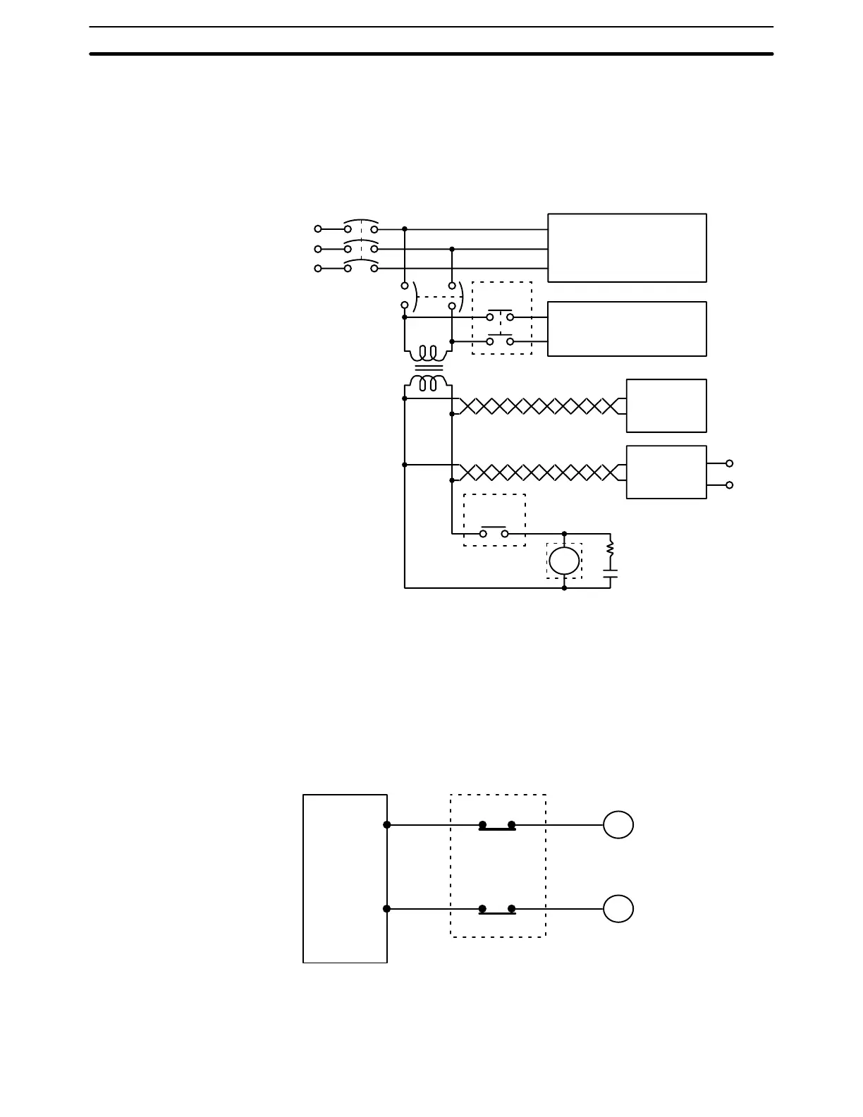
power to the PC OFF in the event of an emergency. An emergency stop routine
in the PC program is not sufficient to ensure safety. The circuit shown below is an
example of an emergency stop circuit. Incorporate the PC RUN output terminal
into an external relay circuit (CR1 in the diagram below) so that a PC breakdown
or malfunction will not affect the entire system.
MCB1
Power section
Control section
CR1
MCB2
PC RUN
output
CR1
PC
DC input/output
Surge
suppressor
Twisted
Transformer
or noise filter
+
–
DC voltage
regulator
4-11-2 Interlock Circuit
When the PC controls an operation such as the clockwise and counterclock-
wise operation of a motor, provide an external interlock such as the one
shown below to prevent both the forward and reverse outputs from turning
ON at the same time.
PC
MC2
MC1
00501
00502
MC1
MC2
Motor clockwise
Motor counterclockwise
Interlock circuit
This circuit prevents outputs MC1 and MC2 from ever both being ON at the same
time. Even if the PC is programmed improperly or malfunctions, the motor is pro-
tected.
System Design and Safety Considerations Section 4-11